FC Circuit Protection Scheme for 3~12kV Auxiliary Power System: Design, Selection, and Application Cases

I.Solution Overview
This solution aims to provide a complete system based on the combination of a high-voltage vacuum contactor (Contactor) and a high-voltage current-limiting fuse (Fuse), collectively referred to as an FC circuit. Designed for medium-voltage systems ranging from 3 to 12 kV, it is particularly suitable for applications requiring frequent operation, high reliability, and cost-effectiveness. In the FC circuit, the vacuum contactor handles the making and breaking of normal and overload currents, as well as frequent operations, while the high-voltage fuse provides robust short-circuit protection. Together, they form a fully functional, high-performance protection and control unit.
II. Characteristics of Core Components
The core advantage of the FC circuit lies in the exceptional performance and precise coordination of its two key components.
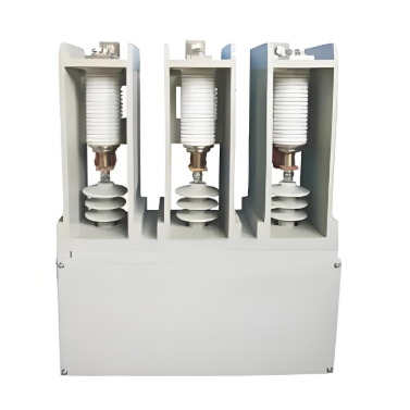
(I) High-Voltage Vacuum Contactor (Operation and Overload Interruption Component)
As the operational core of the circuit, the vacuum contactor exhibits the following characteristics:
- Advanced Structure and Interruption Principle:
- Features a vacuum interrupter chamber (vacuum level up to 1.33×10⁻⁴ Pa) with its main contacts sealed within a ceramic enclosure. During opening, the moving and fixed contacts separate rapidly, leveraging the rapid condensation of metal vapor at current zero-crossing to efficiently extinguish the arc and restore insulation strength.
- Equipped with a linked tripping mechanism that ensures tripping upon the melting of one fuse phase, preventing phase-loss operation, and includes a mis-closing prevention function when fuses are not installed.
- Extremely low chopping current (≤0.5A), effectively suppressing switching overvoltages and protecting the insulation of inductive loads such as motors.
- High-Reliability Operating Mechanism:
- Utilizes an electromagnetic operating mechanism capable of switching frequencies up to 2,000 operations per hour, meeting the most demanding frequent operation requirements.
- Flexible holding methods: Electrical self-holding (maintained by a holding coil after closing, with low power consumption) and mechanical self-holding (e.g., LHJCZR series, mechanically latched after closing, requiring no continuous power supply) are available to suit different control needs.
- Strong compatibility with control power sources, supporting DC/AC 110V/220V.
- Excellent Rated Parameters and Lifespan:
- Key electrical parameters:
|
Parameter Category |
Specific Values |
|
Rated Voltage |
3.6, 7.2, 12 kV |
|
Rated Operating Current |
200, 400, 630 A |
|
Rated Breaking Capacity |
3.2 kA (25 operations) |
|
Rated Making Capacity |
4 kA (100 operations) |
|
Rated Overload Capacity |
6 kA (1s), 4 kA (3s), 2.5 kA (30s) |
- Extended lifespan: Electrical life of up to 300,000 operations and mechanical life of up to 1,000,000 operations, significantly reducing maintenance efforts and lifecycle costs.
- Dedicated vacuum interrupter chambers: Such as the TJC 12/630 type, featuring low loss, low surge, high wear resistance, and a contact resistance of ≤60 μΩ.
(II) High-Voltage Current-Limiting Fuse (Short-Circuit Protection Component)
As the core of short-circuit protection in the circuit, its selection and application are critical.
- Functional Principle: When the current exceeds a specified value for a certain duration, the fuse element melts instantly and interrupts the fault current. Its key characteristic is that the larger the interrupting current, the shorter the operating time, providing strong current-limiting capability.
- Selection Principles:
- Rated voltage: Must be no less than the system's rated voltage; it can be slightly higher but must never be lower.
- Rated current: Must comprehensively consider the circuit's normal operating current, overload current, and equipment starting characteristics (e.g., motor starting current and time). As a backup protection, it operates only when the fault current exceeds the contactor's breaking capacity or if the contactor fails to operate.
- Protection Coordination with Different Equipment:
- High-voltage motors (≤1200 kW): The fuse must withstand the motor's starting current, while overload protection is handled by a comprehensive protection relay. Ensure the fuse's time-current characteristic curve intersects correctly with the relay curve to achieve protection division.
- Example: For a 250 kW motor with a starting time of 6s and starting current of 220A, a 100A fuse element is suitable (for 2-3 starts per hour).
- Transformers (≤1600 kVA): The fuse must withstand inrush currents during energization and sustained overload currents. Selection is directly matched based on the transformer's rated capacity and voltage level.
- Example: For a 10 kV/800 kVA transformer, an 80A fuse is suitable.
- Capacitor banks (≤1200 kvar): Must withstand switching inrush currents, and their let-through energy must be less than the capacitor's withstand capability. The rated current is typically 1.5–2 times the capacitor's rated current. For applications with excessive inrush currents or frequent switching, series reactors are recommended.
III. Application Scope and Typical Cases
(I) Application Scope
- Suitable Scenarios:
- Protection and control circuits for transformers up to 1600 kVA in industrial plants.
- Frequent starting and protection circuits for high-voltage motors up to 1200 kW.
- Switching circuits for capacitor banks up to 1200 kvar.
- Unsuitable Scenarios: For loads exceeding the above capacities, vacuum circuit breaker panels must be used.
(II) Successful Cases
The FC circuit solution has been widely applied in numerous power plant projects, with proven reliability:
- Thermal Power Plant: Utilized 8 vacuum circuit breaker panels + 36 FC panels. Among them, LHJCZR contactors with WFNHO fuses protect motors, while XRNT fuses protect transformers.
- Power Plant: Utilized 10 vacuum circuit breaker panels + 36 FC panels (21 for motor protection, 12 for transformer protection, and 3 for capacitor protection).
IV. Solution Advantages and Conclusion
This FC circuit solution integrates the dual advantages of vacuum contactors and current-limiting fuses, offering the following core benefits:
- Cost-Effectiveness: Significantly lower investment costs compared to vacuum circuit breaker panels, offering high cost-performance.
- Specialized Performance: Contactors excel in frequent operations and overload interruption, while fuses excel in rapidly interrupting high short-circuit currents, ensuring clear division of labor and superior protection.
- Safety and Reliability: Extremely short short-circuit interruption time (millisecond level), excellent current-limiting characteristics, and effective protection of system equipment. The linked tripping mechanism prevents phase-loss operation.
- Maintenance-Free and Long Lifespan: Vacuum interrupter chambers are maintenance-free, with electrical and mechanical lifespans of up to a million operations, significantly reducing lifecycle costs.
- Compact and Flexible Design: Compact structure saves installation space. High versatility allows interchangeability among similar products, facilitating maintenance and spare parts management.
Conclusion: The FC circuit is an ideal choice for the protection of small to medium-capacity transformers, motors, and capacitors in industrial power systems such as power plants, petrochemicals, and metallurgy. This solution is technologically mature, extensively validated, and offers outstanding advantages, making it the best practice for balancing performance, cost, and reliability. For applications exceeding its capacity range, vacuum circuit breaker solutions are recommended.