I. Background and Demand
With the rapid increase in renewable energy adoption, traditional electromagnetic transformers struggle to meet modern grids’ demands for flexibility, efficiency, and intelligence. The volatility and intermittency of wind and solar power pose severe challenges to grid stability, necessitating an innovative energy conversion hub capable of dynamic regulation and high-quality power output.
II. Solution Overview
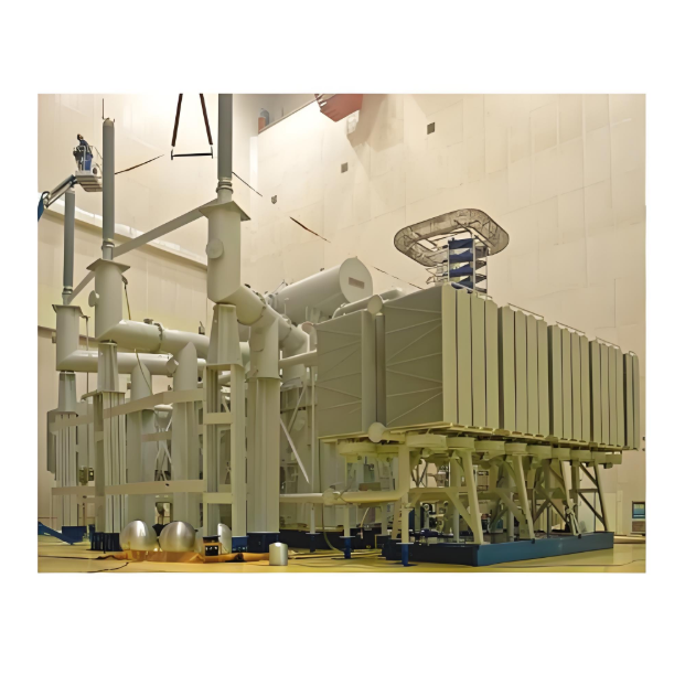
This solution employs all-solid-state Power Electronic Transformers (PETs) to replace conventional line-frequency transformers. Leveraging high-frequency power electronics, PETs enable voltage-level conversion and energy control with core advantages:
Flexible Power Conversion: Breaks the limitations of traditional transformers (voltage/current amplitude only) to achieve multi-dimensional control over frequency, phase, and power.
Dynamic Response: Millisecond-level adjustment speed effectively mitigates renewable energy fluctuations.
Smart Interface: Creates a digital bridge between power generation units and the grid.
III. Core Technical Architecture
1. Multi-Level Topology Optimization
Adopts an "AC-DC-AC" Three-Stage Conversion Architecture:
High-Frequency Rectification Stage: Uses MMC (Modular Multilevel Converter) topology to accommodate wide input voltage fluctuations.
Isolated DC-DC Stage: Implements Dual Active Bridge (DAB) structure for 10-20 kHz high-frequency isolation.
Smart Inversion Stage: Supports dynamic switching of grid-tie strategies (V/f control, PQ control).
2. Key Component Selection
Component |
Technology |
Advantages |
Switching Devices |
SiC MOSFET Modules |
High-temperature resistance (>200°C), 40% loss reduction |
Magnetic Core |
Nanocrystalline Alloy |
60% lower high-frequency losses, 3x power density |
Capacitors |
Metallized Polypropylene Film Caps |
High voltage tolerance, long lifespan, low ESR |
3. Intelligent Control System
Real-time grid status monitoring enables:
Active voltage sag ride-through (LVRT/ZVRT)
Dynamic power flow adjustment for renewable fluctuations
Loss optimization algorithms
IV. Key Benefits and Value
Efficiency Gains
Metric |
Traditional Trafo |
PET |
Improvement |
Full-Load Efficiency |
98.2% |
99.1% |
↑0.9% |
20% Load Efficiency |
96.5% |
98.8% |
↑2.3% |
No-Load Losses |
0.8% |
0.15% |
↓81% |
Functional Capabilities
Active Filtering: Suppresses 5th–50th harmonics (THD <1.5%)
Reactive Compensation: ±100% continuous capacity regulation
Fault Ride-Through: Zero-voltage ride-through (ZVRT) support
Black Start: Autonomous voltage/frequency stabilization in islanded mode
V. Application Scenarios
Scenario 1: Wind Farm Collector System
graph TB
WTG1[WTG1] --> PET1[10kV/35kV PET]
WTG2[WTG2] --> PET1
...
PET1 -->|35kV DC Bus| Collector
Collector --> G[220kV Main Trafo]
Solves: Collector line oscillations from cumulative turbine voltage swings
Results: 12% lower wind curtailment, 65% reduction in power fluctuation deviation
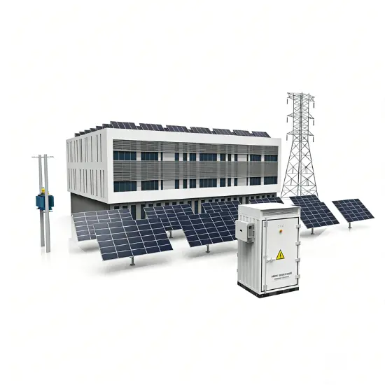
Scenario 2: PV Plant Smart Step-Up Station
Modular PET clusters (1–2 MW/unit)
MPPT functionality enhances yield by 7–15% in partial shading
Nighttime operation as STATCOM for grid reactive support
VI. Implementation Roadmap
Pilot Phase: Deploy PETs at renewables plants with >10% voltage volatility (20% capacity).
Hybrid Grid Stage: Hybrid Transformer System (HTS) with parallel PET-traditional operation.
Full Replacement: PETs for all new projects; phased retrofits for existing plants.
VII. Economic Analysis
Example: 100MW Wind Farm
Item |
Traditional |
PET |
Annual Benefit |
Capex |
¥32M |
¥38M |
-¥6M |
Annual Power Losses |
¥2.88M |
¥1.08M |
+¥1.8M |
O&M Costs |
¥0.8M |
¥0.45M |
+¥0.35M |
Reactive Savings |
— |
¥0.6M |
+¥0.6M |
Payback Period |
— |
<3 Years |
Conclusion: PET solutions break traditional electromagnetic limitations, creating a next-generation power conversion platform for high-renewable grids. Their advantages in efficiency, grid support, and intelligence position them as a strategic technology for modern power systems.