• Product
  • Suppliers
  • Manufacturers
  • Solutions
  • Free tools
  • Knowledges
  • Experts
  • Communities
Search


Innovative Applications of Time Relays in Fault Self-Recovery and Equipment Damage Prevention

In the field of industrial control, time relays are not new components, but their traditional applications are often limited to basic scenarios such as sequential startup and reduced-voltage starting, failing to fully leverage their core value of "precise delay control." Based on practical technical implementation experience, this article addresses common production challenges faced by enterprises and focuses on innovative applications of time relays in two high-frequency problem areas: "fault self-recovery" and "equipment damage prevention." Through two directly reusable industrial cases, it breaks down the entire process from problem diagnosis to solution implementation, providing enterprises with low-cost, highly reliable, and practical solutions.

  1. Application Scenario 1: Automatic Restart of a 75kW Induced Draft Fan After Instant Power Loss
  1. Pain Point: Remote equipment is "easy to stop but difficult to restart."
    A company operates a 75kW large induced draft fan with a control cabinet installed in a remote area. When a momentary power grid fluctuation (e.g., lightning strike) causes a shutdown, the company faces a dilemma:
    • Manual restart is time-consuming: Sending personnel to the site takes too long, disrupting production processes (e.g., furnace pressure) and compromising product quality.
    • Forced restart poses risks: Direct full-voltage startup after the motor speed drops generates high inrush current, damaging equipment and the power grid. Following a full restart procedure takes too long and cannot avoid production interruptions.
  2. Solution: Add a "power-off delay relay" to enable intelligent self-recovery.
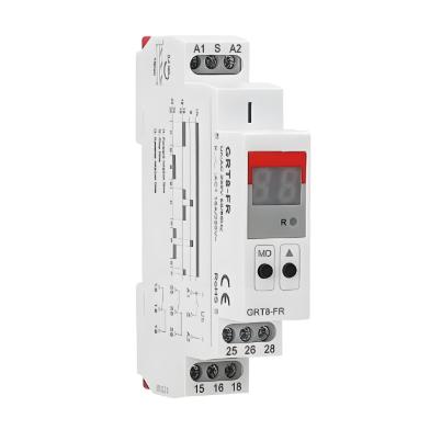
    Without modifying the main cabinet or upgrading the PLC, simply parallel-connect a power-off delay time relay (KT2) to the existing Y-Δ reduced-voltage starting circuit.
  3. Operational Logic (Three-Step Process):
    • Normal operation: KT2 is energized simultaneously with the main contactor, and its "delay-open normally open contact" closes immediately, preparing for automatic restart.
    • Momentary power loss: All components lose power, and KT2 initiates a power-off delay (set time T, e.g., 10 seconds).
    • Power restoration (core decision):
    o If power returns within 10 seconds: KT2 contacts remain closed, the control circuit automatically engages, and the motor immediately executes a Y-Δ startup, enabling unattended rapid production recovery.
    o If power returns after 10 seconds: KT2 contacts have opened, locking out the startup circuit to prevent risky startups and requiring manual inspection for safety.
  4. Application Value:
    • Ensures production continuity: Instant automatic recovery avoids production accidents.
    • Protects equipment: Ensures restart only at safe motor speeds, eliminating inrush current.
    • Saves labor: Eliminates the need for frequent site visits, significantly reducing maintenance costs.
  1. Application Scenario 2: Preventing Frequent Start-Stop of a Hydrogen Pre-Cooler Motor
  1. Pain Point: Critical temperature fluctuations cause motor "chronic suicide."
    The pre-cooler motor is controlled by a temperature sensor. When temperature fluctuates near the set critical point (e.g., 24.8°C–25.2°C), the sensor output frequently toggles, potentially causing the motor to start and stop 3–5 times per minute. The accumulated heat from frequent startups (starting current is 5–7 times the rated current) can easily burn out the motor (replacement costs tens of thousands of dollars), severely violating the manufacturer’s requirement of "no more than 30 starts per hour."
  2. Solution: Add a "power-on delay relay" to enforce startup intervals.
    Without replacing the temperature control system, simply use a power-on delay time relay (KT) to add a "forced delay" checkpoint to the startup command.
  3. Operational Logic (Four-Step Process):
    • First startup: Temperature control signal (K2) closes, triggering an intermediate relay (1KA), which allows the contactor (KM) to energize and start the motor.
    • Normal stop: Temperature drops, K2 opens, 1KA de-energizes, and the motor stops. Meanwhile, the KT coil energizes and begins a power-on delay (e.g., set to 2 minutes).
    • Second request: Temperature exceeds the limit again, K2 closes. However, during KT’s 2-minute delay, its "delay-close contact" remains open, cutting off the startup circuit and preventing motor restart even if the button is pressed.
    • Allow restart: After KT’s delay ends, its contact closes. If the temperature remains too high, the motor can restart.
  4. Application Value:
    • Eliminates risks: Enforces a 2-minute interval, limiting starts to 30 per hour, completely preventing motor burnout, and extending lifespan by 3–5 years.
    • Ultra-low cost: Investment of around $100, no need to modify the original system, implementation takes only 1–2 hours, with an input-output ratio exceeding 1:100.
    • Dual safeguards: Adds "time control" to "temperature control," significantly improving system reliability.
  1. Summary and Implementation Recommendations

The above cases demonstrate that by moving beyond the conventional "sequential control" mindset and flexibly designing "delay logic" around production pain points, the classic time relay can solve major problems at extremely low costs.

Its core advantages include:

  1. Functional flexibility: Using the two basic modes of "power-on delay" and "power-off delay," it can衍生出 diverse complex functions such as self-recovery, anti-frequent start-stop, and sequential protection.
  2. Cost-effectiveness: Costs only 1/10 to 1/50 of solutions using PLCs or frequency converters, and modifications require no overhaul of the main circuit, making it ideal for small and medium-sized enterprises.
  3. Easy maintenance: Pure hardware logic, no software failure risks, and technicians can maintain it based on diagrams.

Implementation Recommendations:
• Scenario suitability: Prioritize applications for "instant fault self-recovery," "action frequency limiting," and "multi-equipment sequential control."
• Parameter setting: Delay times must be scientifically determined (e.g., reference motor speed decay curves for auto-restart, rated start-stop times for anti-frequent stop).
• Environmental selection: Always choose industrial-grade products suitable for harsh conditions such as high temperature, dust, and explosion-proof requirements to ensure long-term reliability.08:07:34

09/20/2025
Recommended
Engineering
Integrated Wind-Solar Hybrid Power Solution for Remote Islands
Abstract​This proposal presents an innovative integrated energy solution that deeply combines wind power, photovoltaic power generation, pumped hydro storage, and seawater desalination technologies. It aims to systematically address the core challenges faced by remote islands, including difficult grid coverage, high costs of diesel power generation, limitations of traditional battery storage, and scarcity of freshwater resources. The solution achieves synergy and self-sufficiency in "power suppl
Engineering
An Intelligent Wind-Solar Hybrid System with Fuzzy-PID Control for Enhanced Battery Management and MPPT
Abstract​This proposal presents a wind-solar hybrid power generation system based on advanced control technology, aiming to efficiently and economically address the power needs of remote areas and special application scenarios. The core of the system lies in an intelligent control system centered around an ATmega16 microprocessor. This system performs Maximum Power Point Tracking (MPPT) for both wind and solar energy and employs an optimized algorithm combining PID and fuzzy control for precise
Engineering
Cost-Effective Wind-Solar Hybrid Solution: Buck-Boost Converter & Smart Charging Reduce System Cost
Abstract​This solution proposes an innovative high-efficiency wind-solar hybrid power generation system. Addressing core shortcomings in existing technologies—such as low energy utilization, short battery lifespan, and poor system stability—the system employs fully digitally controlled buck-boost DC/DC converters, interleaved parallel technology, and an intelligent three-stage charging algorithm. This enables Maximum Power Point Tracking (MPPT) over a wider range of wind speeds and s
Engineering
Hybrid Wind-Solar Power System Optimization: A Comprehensive Design Solution for Off-Grid Applications
Introduction and Background​​1.1 Challenges of Single-Source Power Generation Systems​Traditional standalone photovoltaic (PV) or wind power generation systems have inherent drawbacks. PV power generation is affected by diurnal cycles and weather conditions, while wind power generation relies on unstable wind resources, leading to significant fluctuations in power output. To ensure a continuous power supply, large-capacity battery banks are necessary for energy storage and balance. However, bat
Send inquiry
Download
Get the IEE Business Application
Use the IEE-Business app to find equipment, obtain solutions, connect with experts, and participate in industry collaboration anytime, anywhere—fully supporting the development of your power projects and business.