Control Solution for Automatic Feeding Mechanism of Production Line Based on Time Relay

I.Solution Overview
This solution aims to design a stable, efficient, and economical electrical control system for the automatic feeding mechanism of a production line. As the starting unit of the production line, the core task of this mechanism is to automatically and orderly push workpieces from the storage bin to the material platform, maintain them there for a predetermined time, and then supply them to the next workstation. The core of the solution involves selecting a DC electromagnetic time relay to achieve precise 2-second delay control of the workpieces on the material platform, ensuring accurate production rhythm.
II. Key Component Selection and Analysis
Time Relay (Core Control Component)
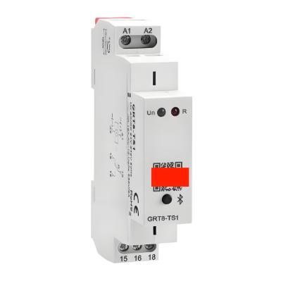
- Selection: DC electromagnetic time relay.
- Selection Basis:
- Adaptability: The feeding mechanism of the production line features high repetitiveness and frequent operation. The DC electromagnetic relay, with its simple structure, long service life, and high allowable actuation count, perfectly meets this high-frequency demand.
- Economy: Compared to synchronous motor-type relays, it is more cost-effective, helping to reduce overall costs.
- Functional Match: The required 2-second delay falls within its typical delay range (0.3–5.5 seconds), and the power-off delay function required in this solution is a specialty of the DC electromagnetic type.
Working Principle: In this solution, its power-off delay characteristic is utilized. After the pushing cylinder completes its action (trigger signal disappears), the time relay coil is de-energized, and its power-off delay contacts start timing. After a 2-second delay, the contacts actuate, sending a signal to allow the next cycle to begin or to start the conveying mechanism.
Cylinder with Magnetic Switch (Position Detection and Actuator)
- Function: Precisely detects the piston positions of the pushing and clamping cylinders (extended and retracted limits), providing feedback signals to the PLC or control circuit, serving as the foundation for sequential process control.
- Key Features: Easy installation and adjustment, with detection points set via sliding and tightening bolts; blue wire connects to the common terminal, brown wire to the signal terminal, following wiring standards.
Single Solenoid-Controlled Directional Valve (Directional Control Component)
- Function: Receives control signals to switch the direction of compressed airflow, thereby controlling the extension and retraction of the pushing and clamping cylinders.
- Working Principle: When the solenoid coil is energized, it drives the spool to switch, actuating the cylinder; when de-energized, the spring resets the spool, causing the cylinder to reverse or maintain its position.
Proximity Sensor (Auxiliary Detection Component)
- Function: Can be used to detect whether a workpiece is present on the material platform, serving as a trigger signal for the time relay to start timing or as a safety verification signal after timing completion.
III. Working Process and Control Logic of the Feeding Mechanism
Combining the above components, the automated workflow of the feeding mechanism is as follows:
- Initial State: The storage bin is filled with workpieces; the pushing cylinder piston rod is retracted (at the bottom of the bin), and the clamping cylinder piston rod is retracted.
- Trigger Clamping: The system starts, and the single solenoid-controlled directional valve activates the clamping cylinder piston rod to extend, pressing against the sub-layer workpiece to prevent the entire stack from falling.
- Execute Pushing: After clamping is confirmed (detected by the magnetic switch), another single solenoid-controlled directional valve activates the pushing cylinder piston rod to extend, accurately pushing the bottom-layer workpiece to the material platform.
- Pushing Return: Once the pushing cylinder reaches the front limit position (detected by the magnetic switch), the solenoid valve is de-energized, and the cylinder piston rod automatically retracts.
- Delay Start: After the pushing cylinder fully retracts (rear magnetic switch detects the signal), this signal disappearance (power-off) serves as the input signal for the time relay. The time relay begins its 2-second power-off delay.
- Release and Feeding: During the time relay delay, the workpiece remains stationary on the material platform, meeting the process requirement of a 2-second stabilization time. After the delay ends, the power-off delay contacts of the time relay actuate.
- Option A (Interlocked Control): This signal is used to de-energize the solenoid valve of the clamping cylinder, causing its piston rod to retract and release the workpiece.
- Option B (Sequential Control): This signal can serve as a trigger condition for the next action (e.g., starting the conveying mechanism or initiating the next feeding cycle).
- Cycle Completion: After the clamping cylinder releases, the entire stack of workpieces descends by one position under gravity, with the bottom-layer workpiece in place. The mechanism returns to its initial state, awaiting the next start signal, and the cycle repeats.
IV. Core Role of the Time Relay
In the control circuit of this solution, the time relay is critical for achieving the core functionality:
- Function Implementation: Specifically responsible for fulfilling the process requirement of "maintaining the workpiece on the material platform for 2 seconds."
- Operation Mode: Utilizes the power-off delay mode. Its timing starts when the pushing cylinder confirms retraction (signal disappearance) and ends 2 seconds later with an output signal to control subsequent actions.
- Advantage: This design ensures the delay starts only after the workpiece is successfully pushed and the pushing cylinder safely retracts, making the logic rigorous, safe, and reliable.


