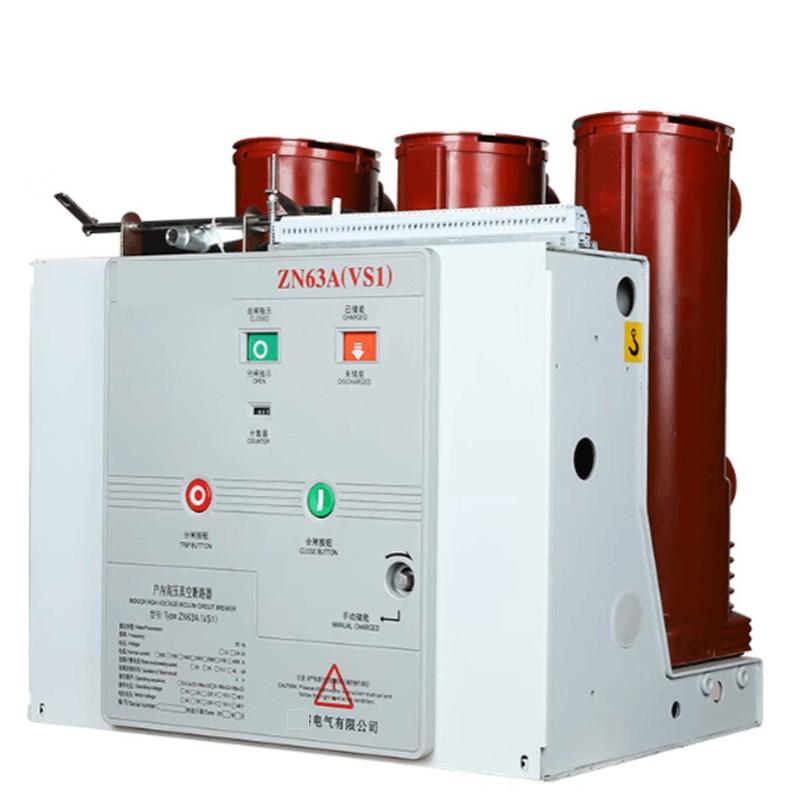
The selection and installation of current transformers for air-insulated switchgear (AIS CT) directly affect the measurement accuracy, protection reliability, and operational safety of power systems. It is necessary to comprehensively consider equipment characteristics, system requirements, and environmental conditions. The specific precautions are as follows:
1. Precautions for Selection
1.1 Matching of Electrical Parameters
Rated primary current: Determine based on the maximum continuous operating current of the circuit where it is located. Generally, it is selected as 1.2-1.5 times the rated current of the circuit to ensure no overheating or overload during long-term operation. For example, if the rated current of a 10kV line is 400A, a CT with 500A/5A can be selected.
Rated secondary current: It needs to match secondary equipment (instruments, relays, etc.), with common values being 5A or 1A (1A is suitable for long-distance transmission with smaller losses).
Accuracy class and accuracy limit factor (ALF):
Measurement-purpose CTs must meet the accuracy class (such as 0.2, 0.5) to ensure metering precision.
Protection-purpose CTs should focus on the accuracy limit factor (such as 5P20, 10P30) to ensure that the secondary current error is within the allowable range during short circuits (5P20 means that when the short-circuit current is 20 times the rated primary current, the error is ≤5%).
Rated voltage: It must be consistent with the rated voltage of the AIS equipment (such as 10kV, 35kV, 110kV) and meet the insulation level requirements (such as lightning impulse withstand voltage, power frequency withstand voltage).
1.2 Adaptability of Structural Form
Installation method: Select post-type, through-wall type, or busbar type according to the layout of AIS equipment. Post-type is suitable for outdoor open layout; through-wall type is used for passing through walls or switchgear partitions; busbar type is directly sleeved on the busbar, with a compact structure.
Number of windings: Choose single-winding (only for measurement or only for protection) or multi-winding (to meet functions such as measurement, protection, and metering simultaneously, with different windings corresponding to different accuracy classes) according to secondary needs.
Shell material: For outdoor use, materials with strong weather resistance (such as silicone rubber, porcelain) should be selected; for indoor use, epoxy glass fiber, etc., can be used to avoid rust or aging affecting insulation.
1.3 Environmental Adaptability
Climatic conditions: For outdoor installation, factors such as temperature range (-40℃~60℃), humidity, altitude (insulation needs to be strengthened in high-altitude areas, e.g., insulation strength needs to be increased by 20% at an altitude of 3000m), and pollution level (products with large creepage distance should be selected in heavily polluted areas, with creepage distance ≥25mm/kV) must be considered.
Mechanical strength: It must withstand mechanical stresses such as earthquakes and wind forces, especially for post-type CTs installed outdoors at high heights, which must meet anti-overturning and anti-seismic grade requirements.
2. Installation Precautions
2.1 Inspection Before Installation
Appearance and insulation: Check that the porcelain sleeve/shell is free of damage and cracks, and the insulation surface is clean; measure the insulation resistance with a 2500V megohmmeter, which should be ≥1000MΩ (at room temperature).
Parameter verification: Confirm that the CT's model, rated current, accuracy class, and other parameters are consistent with the design drawings, and the nameplate is clear and complete.
Test report: A factory test report (such as transformation ratio test, volt-ampere characteristic test, polarity test) must be provided to ensure qualified performance.
2.2 Installation Specifications
Correct polarity: The primary side "L1" (incoming end) and the secondary side "K1" (outgoing end) of the CT must maintain consistent polarity (subtractive polarity) to avoid misoperation of the protection device or reverse measurement. Polarity can be confirmed by the DC method or instrument testing.
Grounding requirements:
The shell must be reliably grounded (single-point grounding) with a grounding resistance ≤4Ω to prevent electric shock hazards from live shells.
The "K2" end of the secondary winding must be reliably grounded to avoid high voltage generated by an open secondary side (the secondary side of the CT is strictly prohibited from being open; the secondary winding must be short-circuited first during installation).
Installation position:
It should be as close as possible to the circuit breaker or disconnector to shorten the length of the connecting wire and reduce measurement errors.
Avoid arranging it in close proximity to strong magnetic field equipment (such as reactors) to prevent electromagnetic interference from affecting accuracy.
Connection tightness: The primary side terminal must be tightened (meeting torque requirements) to prevent heating; the cross-sectional area of the secondary side wire should be ≥2.5mm², and the wiring should be firm to avoid poor contact due to looseness.
2.3 Safety Protection
Anti-open circuit measures: During installation or maintenance, the secondary winding must be short-circuited first (with a special shorting piece). It is strictly prohibited to disconnect the secondary circuit in a live state (an open secondary side will generate thousands of volts of high voltage, endangering equipment and personal safety).
Clear identification: Mark the polarity, transformation ratio, and winding purpose on the CT body and the secondary circuit end cover to avoid wrong wiring.
2.4 Calibration After Installation
Transformation ratio review: Confirm that the primary and secondary current transformation ratios are consistent with the design through tests.
Insulation test: Measure the insulation resistance again after installation to ensure that the insulation is not damaged during the installation process.
Overall debugging: Conduct linkage tests with AIS equipment and secondary protection devices to verify the correctness of protection actions (such as overcurrent protection, differential protection).
3. Subsequent Maintenance Points
Regularly clean the insulation surface (especially for outdoor equipment) to remove dirt, bird droppings, etc., to prevent flashover.
Check whether the grounding connection is loose and whether the shell is rusted or leaking oil (oil-immersed CT).
Conduct preventive tests (such as dielectric loss test, partial discharge test) every 3-5 years to evaluate the degree of insulation aging.
By strictly following the selection standards and installation specifications, AIS CT can achieve accurate measurement and reliable protection in the power system, and extend the service life of the equipment.