• Product
  • Suppliers
  • Manufacturers
  • Solutions
  • Free tools
  • Knowledges
  • Experts
  • Communities
Search


Ground Fault vs Earth Fault: Understanding the Differences and Protection Methods

Edwiin
Field: Power switch
China

What is a Ground Fault and an Earth Fault?

Ground Fault:

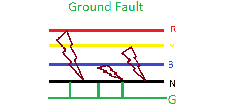
A ground fault occurs when an unintended connection (fault) develops between a live conductor and the ground or neutral point. In such a fault, the current flows directly to the ground. This can happen in various forms, such as a single line-to-ground fault (L-G), double line-to-ground fault (LL-G), or three line-to-ground fault (LLL-G).

Ground faults are particularly severe because they can result in a large magnitude of fault current. If not cleared promptly within the specified time, this high current can cause significant damage to power system equipment, including transformers, cables, and switchgear. Therefore, rapid detection and isolation of ground faults are critical for system protection and safety.

Note:

The ground point must be properly connected to the source and effectively grounded. Additionally, when a live conductor comes into contact with the ground (e.g., falls to earth), it creates an unintended path to ground. This condition is typically referred to as an earth fault—a type of open-circuit or leakage fault where current flows from the conductor into the earth.

Causes of Ground Faults:

  • Insulation failure: Degradation or loss of dielectric properties in insulation due to aging, overheating, or contamination.

  • Physical damage to underground cables: Mechanical damage during excavation or construction, or water ingress into cable trenches, leading to insulation breakdown.

  • Cable overload: Excessive current causing overheating, which may melt or sever the conductor, allowing it to contact the ground.

  • Natural disturbances:

    • Trees falling onto power lines.

    • Water accumulation or flow over insulators, causing flashover.

    • Animals or birds simultaneously touching a live conductor and a grounded structure, creating a conductive path.

Protection Against Ground Faults:

To safeguard the power system, protective relays are employed to detect abnormal conditions and initiate tripping of the associated circuit breaker.

Instrument transformers—such as Current Transformers (CTs) and Potential Transformers (PTs)—are used to measure system current and voltage, respectively. These signals are fed to protective relays, which compare the measured values against pre-set thresholds.

If the current or voltage exceeds the preset limit, the relay activates, sending a trip signal to the circuit breaker to isolate the faulty section and clear the fault.

Common relays used for ground fault protection include:

  • Current-based relays:

    • Overcurrent Relay

    • Instantaneous Overcurrent Relay

    • Earth Fault Relay

  • Voltage-based relays:

    • Overvoltage Relay

    • Overfluxing Relay

Earth fault:

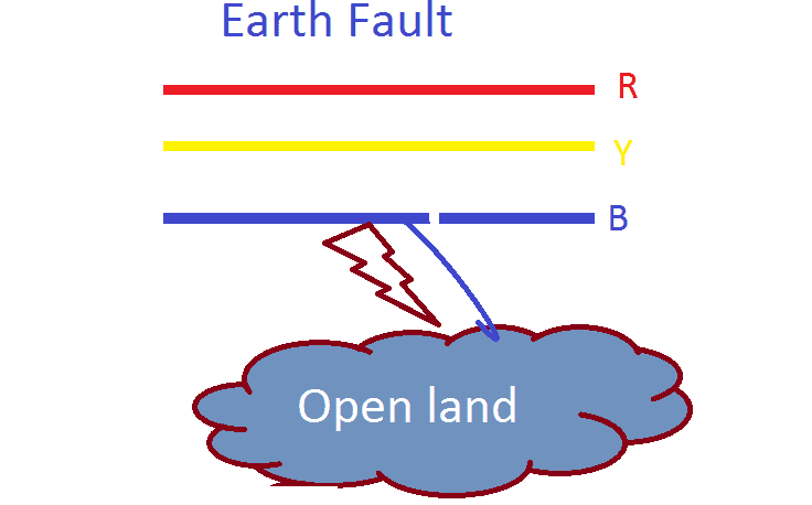
An earth fault is a type of open-circuit fault that occurs when a current-carrying cable or conductor breaks and comes into contact with the earth or with a conductive material that is in contact with the earth. In such a scenario, under radial power flow conditions, the load end of the system becomes disconnected from the source.

Give a tip and encourage the author!

Recommended

Why Must a Transformer Core Be Grounded at Only One Point? Isn't Multi-Point Grounding More Reliable?
Why Does the Transformer Core Need to Be Grounded?During operation, the transformer core, along with the metal structures, parts, and components that fix the core and windings, are all situated in a strong electric field. Under the influence of this electric field, they acquire a relatively high potential with respect to ground. If the core is not grounded, a potential difference will exist between the core and the grounded clamping structures and tank, which may lead to intermittent discharge.I
01/29/2026
Understanding Transformer Neutral Grounding
I. What is a Neutral Point?In transformers and generators, the neutral point is a specific point in the winding where the absolute voltage between this point and each external terminal is equal. In the diagram below, pointOrepresents the neutral point.II. Why Does the Neutral Point Need Grounding?The electrical connection method between the neutral point and earth in a three-phase AC power system is called theneutral grounding method. This grounding method directly affects:The safety, reliabilit
01/29/2026
Voltage Imbalance: Ground Fault, Open Line, or Resonance?
Single-phase grounding, line break (open-phase), and resonance can all cause three-phase voltage unbalance. Correctly distinguishing among them is essential for rapid troubleshooting.Single-Phase GroundingAlthough single-phase grounding causes three-phase voltage unbalance, the line-to-line voltage magnitude remains unchanged. It can be classified into two types: metallic grounding and non-metallic grounding. Inmetallic grounding, the faulted phase voltage drops to zero, while the other two phas
11/08/2025
Composition and Working Principle of Photovoltaic Power Generation Systems
Composition and Working Principle of Photovoltaic (PV) Power Generation SystemsA photovoltaic (PV) power generation system is primarily composed of PV modules, a controller, an inverter, batteries, and other accessories (batteries are not required for grid-connected systems). Based on whether it relies on the public power grid, PV systems are divided into off-grid and grid-connected types. Off-grid systems operate independently without relying on the utility grid. They are equipped with energy-s
10/09/2025
Send inquiry
+86
Click to upload file
Download
Get the IEE Business Application
Use the IEE-Business app to find equipment, obtain solutions, connect with experts, and participate in industry collaboration anytime, anywhere—fully supporting the development of your power projects and business.