1. Overview of Components and Issues
TA (low-voltage current transformer) and electric energy meters are key components of low-voltage electric energy metering. The load current of such meters is no less than 60A. Electric energy meters vary in type, model, and anti-DC performance, and are connected in series in the metering device. Due to the lack of anti-DC capability, they suffer from metering errors under DC component loads, usually caused by non-linear loads. With the increasing use of DC or silicon-controlled equipment, especially in electrified railways and the plastics industry, the risk of DC components has risen. Analyzing low-voltage anti-DC current transformers and detection devices is of great significance for addressing this issue.
2. Reasons for TA Inaccuracy Caused by DC Components
The widespread DC bias in low-voltage current transformers stems from the influence of primary-side DC components. Theoretically, harmonics generated by DC disrupt metering transmission, and changes in the iron core's excitation current fail to produce corresponding magnetic flux changes, ultimately leading to TA inaccuracy. Using half-wave current tests (32% of DC components are half-wave currents), the magnetic permeability decreases after the primary winding, significantly increasing errors (with a negative shift, approaching saturation). Displacement of the secondary winding amplifies waveform changes. Tests show that half-wave currents cause large, geometrically increasing errors in traditional transformers; even tiny DC components can affect low-voltage anti-DC transformers, resulting in errors exceeding the allowable range.
3. R&D of Anti-DC Low-Voltage Current Transformers
Traditional low-voltage transformers use annular magnetic cores (mainly amorphous ribbons, with high magnetic permeability, low saturation coefficients, and unaffected by primary-side DC). Iron-based amorphous cores, though slightly lower in magnetic permeability, are widely used in power transformers due to low iron loss. They have strong initial magnetic susceptibility and low coercivity, with excellent anti-DC capability. Electric waves from the secondary winding can restore the primary current waveform. By combining the complementary magnetic properties of iron-based amorphous and ultra-microcrystalline materials to form composite cores, the metering accuracy of traditional low-voltage anti-DC transformers can be improved.
4.Research on TA anti-DC performance detection methods
The existing anti-DC low-voltage current transformers generally have the problem of lack of detection methods. The previous standards are not standardized and cannot be judged according to unified rules and specifications. Therefore, how to do a good job in the anti-DC performance detection method and optimize it is urgent.
4.1 Comparison of electric energy
After using the low-voltage current transformer, the internal performance of the AC electric energy meter will change, and the proportion of even harmonics will also change. To conduct a clear assessment of it, a half-wave rectification electric energy comparison test line must be applied. Before the test, the half-wave rectification electric energy comparison method experimental line should be appropriately improved based on the actual situation to ensure that it is consistent with the anti-DC performance of the low-voltage current transformer, thereby improving the accuracy of electric energy detection.
4.2 1/1 self-calibration
The circuit diagram selected for this test is based on the data of JJ G1021-2007 "Regulations for the Verification of Power Transformers", and the details are shown in Figure 1.
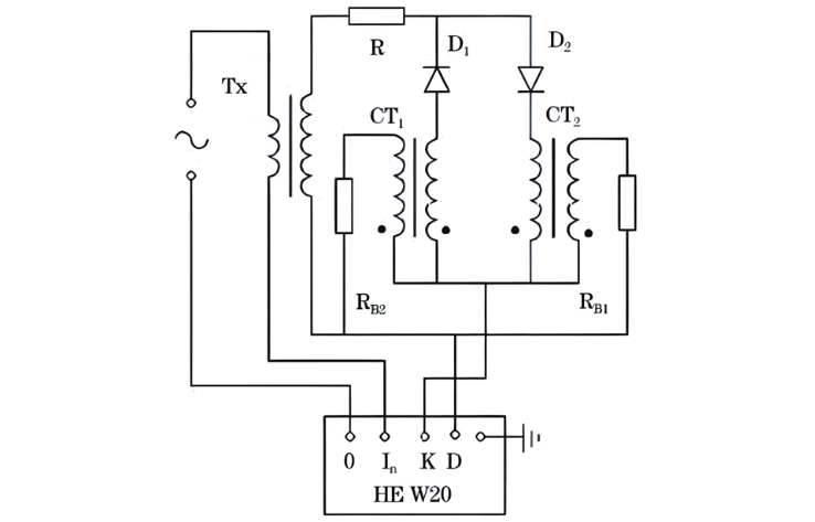
To optimize the 1/1 self - calibration, the experiment rewinds the secondary winding with the same turns as the test low - voltage current transformer. This avoids error introduction from standard transformers. The circuit measures half - wave current and clarifies errors. Note: the current transformer in the circuit uses a 10/1 ratio to boost the verifier’s current, so test values must be multiplied by 10 for accuracy.
Experiments prove this method effectively detects anti - DC performance, enabling circuit testing and self - calibration while avoiding measurement errors. However, rewinding is needed before measurement. Current and detection efficiency are inversely related: as current rises, efficiency plummets but labor intensity increases. Thus, half - wave DC composite error can’t accurately reflect individual anti - DC performance.
5. Test Verification
5.1 Test Method
Simulating half - wave DC electricity theft by electric furnace users, the test installs three distinct energy metering devices. Repeated comparisons of performance results show manganin - resistance energy meters have superior anti - DC shunting ability, meeting on - site stability needs.
5.2 Test Data
Adequate prep, scientific plans, and pre - test site verification are key. During 80 - day assessments, energy is repeatedly compared/calculated, with detailed records.Results: Initial ordinary transformer meters show 40.08% relative error, rising to 90.58% after 80 days. Manganin meters keep errors ≤1% even in harsh conditions, while traditional devices exceed 90% over time. Enhancing anti - DC transformer research is vital for on - site demands.
6. Conclusion
The new composite - core low - voltage anti - DC current transformer accurately measures current, meeting standards even under DC loads. Unlike traditional designs, it retains familiar winding/pouring processes for easy promotion.DC - AC standard - based transformers offer strong operability, solving traceability issues and boosting detection accuracy.