
1 Introduction
Low - voltage current transformers for metering, with a through - core type epoxy resin structure, are widely used in distribution transformer areas and for small - to - medium - sized industrial and commercial electricity consumption. As a range expander for electric energy metering, their performance directly relates to electricity consumption safety and the accuracy of users' trade calculations. Studying long - term immersion's impact on these transformers is practically significant for determining the quality of numerous low - voltage transformers flooded by extreme rain and floods.
Research on transformer moisture absorption has long been ongoing. Existing results haven't covered long - term immersion conditions, and long - term immersion deteriorates current transformers more severely than moisture absorption. In the national standard type test for current transformers, only indoor transformers' protection level is IP20 and outdoor ones' is IP44; power industry and grid company technical standards haven't specified it. To determine if immersed transformers can still be used, this paper conducts a simulated immersion test, analyzes performance changes post - immersion, and offers quality supervision suggestions to improve transformers' waterproofing.
2 Theoretical Analysis of Transformer Immersion Characteristics
The main characteristics of low-voltage current transformers are insulation characteristics and metering characteristics. The insulation characteristics mainly include insulation resistance and power frequency withstand voltage, and the metering characteristics are reflected in the basic error. The immersion characteristics refer to the changes in insulation resistance, power frequency withstand voltage, and basic error of the transformer before immersion and after immersion and drying.
2.1 Insulation Resistance
The insulation resistance R is composed of volume resistance Rv and surface resistance Rs, as shown in formula (1). The volume resistivity ρv and surface resistivity ρs are shown in formulas (2) and (3).
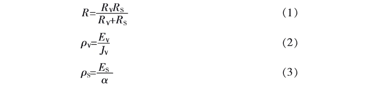
In the formula, EV is the DC electric field strength inside the insulating material; JV is the steady - state current density; ES is the DC electric field strength; α is the linear current density.
Insulation resistance is greatly affected by humidity. Since the electrical conductivity of water is much higher than that of epoxy resin insulating materials, and water has a large dielectric constant, which can reduce the ionization energy of ions. Therefore, when the insulating material is immersed in water, the surface resistivity decreases rapidly, while the volume resistivity changes little; when the immersed material is dried, if the water resistance of the medium material is general or there are defects inside the cast body, the surface resistivity recovers quickly, but the volume resistivity decreases significantly and cannot be effectively restored.
2.2 Power Frequency Withstand Voltage
The test voltage for power frequency withstand voltage is applied between the secondary terminal, the bottom plate and the ground. When in a non - uniform electric field, the breakdown field strength of the medium can be approximately calculated by formula (4).

In the formula, EBD is the breakdown field strength (peak value) between the two electrodes of the insulating material; UBD is the dielectric breakdown voltage (effective value); s is the breakdown distance, and η is the electric field utilization coefficient.
2.3 Basic Error
The basic errors of a current transformer include ratio error and phase error. Regardless of the working condition, the basic error must not exceed the error limit value corresponding to the accuracy level specified in the standard before it can be used.
3 Test Conditions
3.1 Selection of Test Samples
Randomly select the epoxy resin - insulated low - voltage current transformers to be tested, and conduct two groups of tests successively. The test grouping and parameters of the test samples are shown in Table 1.

3.2 Test Equipment
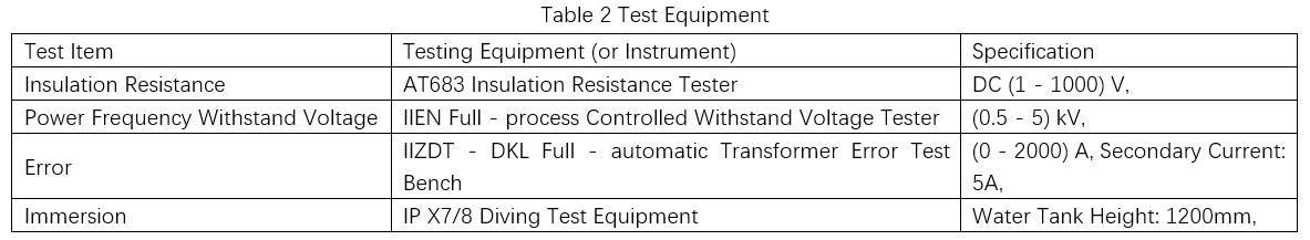
The equipment and parameters used in the test are shown in Table 2.
3.3 Immersion Test
According to the IPX8 regulation in GB/T 4208 - 2017 "Degrees of Protection Provided by Enclosures (IP Codes)", the test is carried out with clean water. For enclosures with a height less than 850 mm, the lowest point shall be 1000 mm below the water surface. Before the test, first measure the insulation resistance, power - frequency withstand voltage, and basic error of the test sample, and then carry out the immersion test.
In the first group of tests, 3 test samples from the same manufacturer were placed into the diving test equipment. Tap water was injected, with the liquid level height being 1000 mm and the water temperature at 15 °C. After being immersed in water for 5 days, they were taken out. The water droplets on them were wiped off with a dry cloth, and they were left to stand for 15 minutes. After drying, tests were carried out. Subsequently, tests were conducted once every day for 10 days. Finally, they were aired at room temperature for 5 days, and tests were performed again after air - drying. For the second group of tests, the sample size was increased. Test samples from 5 randomly selected manufacturers were directly immersed in water for 10 days, then aired for 5 days, and tested again after air - drying.
3.4 Test Data
3.4.1 Insulation Resistance
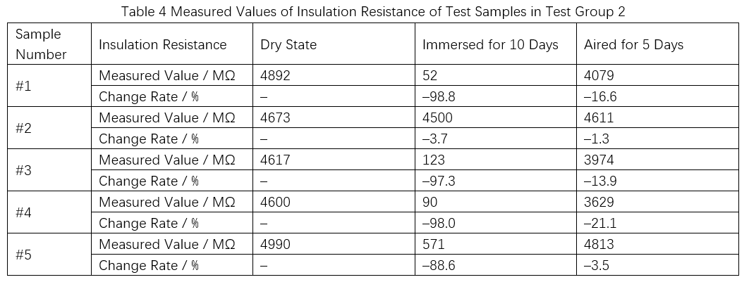
The insulation resistance was measured using the 500V DC voltage range. The insulation resistance values (partial) of the two groups of tests are shown in Table 3 and Table 4.

The #3 test sample had the largest insulation resistance change rate. After being immersed in water for 10 days, the insulation resistance was 43.3 MΩ. After being aired for 5 days, the insulation resistance was 46.0 MΩ, and the change rate reached - 99%. After the immersion test and drying, the insulation resistances of the remaining 7 test samples all recovered to the order of magnitude of the insulation resistance in the initial dry state.
3.4.2 Power - frequency Withstand Voltage
There were a total of 8 test samples in the two groups of tests before and after. Among them, 7 passed the power - frequency withstand voltage test. Only the #3 test sample had difficulty in voltage boosting during the test, and a very obvious discharge sound could be heard. After the test, obvious water traces were found inside the joint between the bottom plate and the epoxy resin of the #3 test sample. There was an obvious gap at the pouring interface of the bottom plate resin of this test sample. The bottom plate of the test sample after the test is shown in Figure 1. In a wet environment with water immersion, external moisture enters the inside of the main body through the gap and cannot be discharged, resulting in a reduction in the insulation level.

3.4.3 Basic Error
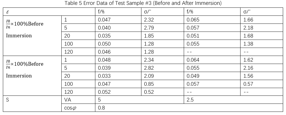
Error tests were conducted on 8 test samples both before and after immersion. Taking test sample #3 as an example, the error test data are shown in Table 5.
4 Test Analysis
Low - voltage current transformers mainly consist of insulating materials, iron cores, and windings. They use a casting process: epoxy resin, silicon micropowder, toughening agents, accelerators, and curing agents are mixed in specified proportions, stirred evenly, and injected into molds under certain conditions for solidification.
4.1 Insulation Resistance
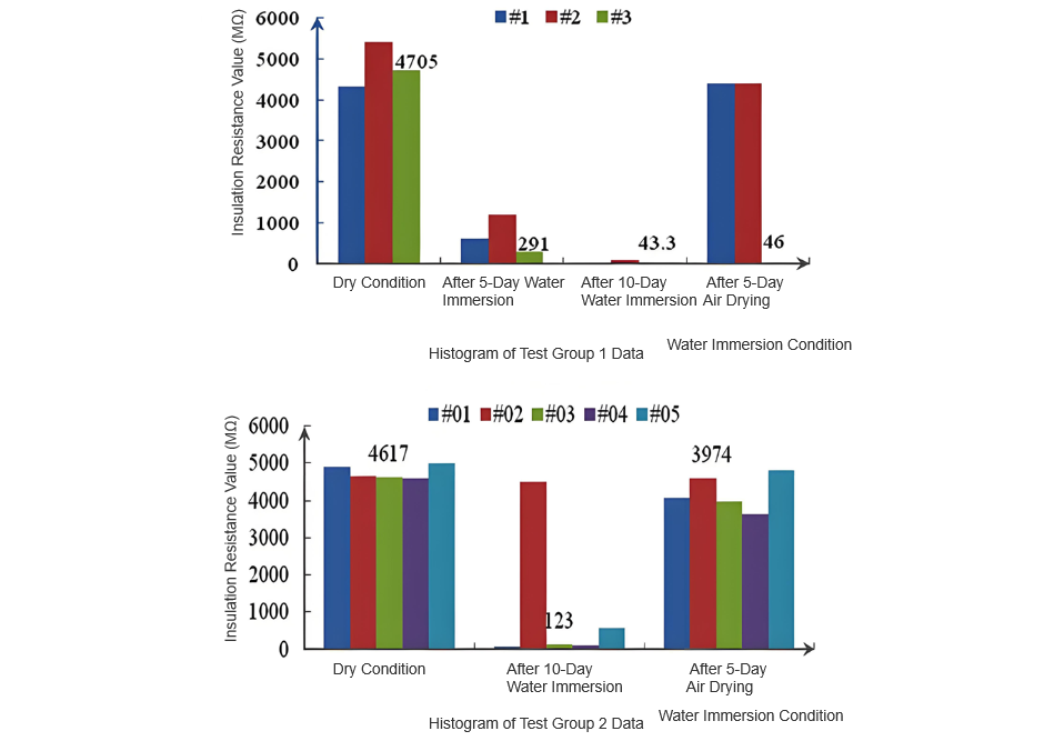
Figure 2 is a histogram of insulation resistance data distribution of current transformers in different test groups. Most tested transformers show consistent insulation resistance changes after immersion and drying: a significant initial drop during immersion, then a rise back to the original dry - state order of magnitude after drying. Only test sample #3 has a - 99% insulation resistance change rate after drying, close to the 30 MΩ qualified critical value.
For Test Group 2 samples, insulation resistance changes vary after immersion. #01, #03, #04, #05 drop to the critical value; #02 remains almost unchanged. After 5 - day drying, they mostly return to the original resistance level, showing #02 has excellent insulation casting quality with no water penetration after long - term immersion.
Temperature (negligible here) and humidity affect insulation resistance. Humidity changes greatly pre - and post - test. Normally, surface resistivity drops while volume resistivity stays. But if the insulating material has low water resistance or casting defects, the main insulation medium absorbs water. Even after drying, internal water hardly evaporates. Surface resistivity recovers, but volume resistivity plummets irrecoverably, lowering overall insulation resistance.
4.2 Power Frequency Withstand Voltage
Epoxy resin - insulated low - voltage current transformers have a large insulation margin. Normally, surface moisture doesn’t cause surface discharge, and they pass the power frequency withstand voltage test after immersion and drying.
However, tiny pores in the insulation medium let water molecules enter after immersion, forming water - filled micropores and turning the solid dielectric into a solid - liquid composite. Water in micropores polarizes and deforms under the electric field, changing from spherical to ellipsoidal, connecting channels and reducing breakdown field strength. More water and denser channels with longer immersion increase breakdown risk. Air gaps in casting also let water in. These factors cause discharge sounds during withstand voltage, as seen in test sample #3.
4.3 Basic Error
A transformer’s error depends only on the core’s magnetic properties and winding parameters. Pre - and post - immersion, the core’s excitation characteristics and winding impedance stay unchanged, and test data show minimal basic error variation.
Immersion tests also revealed:
5 Quality Supervision Suggestions
To avoid severe insulation failure after immersion amid frequent extreme weather, suggestions include:
6 Conclusions
This study addresses quality assessment of epoxy - insulated low - voltage current transformers after heavy rain immersion. Key findings:
These results guide power companies and manufacturers in assessing/reusing long - immersed transformers.


