• Product
  • Suppliers
  • Manufacturers
  • Solutions
  • Free tools
  • Knowledges
  • Experts
  • Communities
Search


Working Principle and Arc Extinction Mechanism of Magnetic Blowout Device in DC Circuit Breakers

Felix Spark
Field: Failure and maintenance
China

The arc extinguishing system of a DC circuit breaker is crucial for the safe operation of equipment, as the arc generated during current interruption can damage contacts and compromise insulation.

In AC systems, the current naturally passes through zero twice per cycle, and AC circuit breakers take full advantage of these zero-crossing points to extinguish the arc.

However, DC systems lack natural current zero crossings, making arc extinction significantly more difficult for DC circuit breakers. Therefore, DC circuit breakers require dedicated arc-blowing coils or permanent magnet arc-blowing techniques to forcefully drive the DC arc into the arc chute, where the arc is split, stretched, and its voltage increased, leading to rapid cooling and accelerated extinction.

Currently, the arc extinguishing device in DC switchgear mainly consists of two key components: the arc-blowing coil (electromagnet) and the controller.The controller is primarily responsible for acquiring the current signal and, when the current reaches the operating threshold of the magnetic blowout device, sending an output signal to power the electromagnetic coil.

The arc-blowing coil (electromagnet) generates an upward mechanical force (Ampere force) according to the current output from the controller, driving the arc into the arc chute.

Below, we focus on how to simply verify, during operation & maintenance or commissioning of new lines, the accuracy of the polarity (N and S poles) of the arc-blowing coils (electromagnets) in DC incoming and outgoing feeder circuit breakers as set at the factory, ensuring an upward force is produced to pull the arc into the arc chute for correct and effective arc extinction.

I. DC Incoming Feeder Cabinet

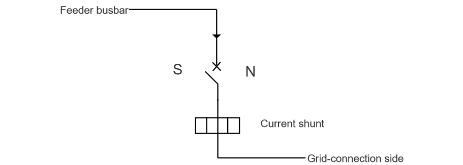
How to determine the accuracy of the magnet polarity: the magnet on the left should be N-pole, and the one on the right should be S-pole.

As shown in the figure below: according to the left-hand rule, given the direction of current (I) and the direction of the Ampere force (F) acting on it (upward), the direction of the magnetic flux density (B)—which points from the N-pole—can be determined. Therefore, the magnet on the left side of the incoming feeder cabinet should be N-pole, and the one on the right should be S-pole.

image.png

Apply a millivolt-level voltage across the shunt to activate the magnetic blowout device. Then, bring a standard magnet (with known polarity) into contact with the magnets in the incoming feeder cabinet. Based on the principle that like poles repel and opposite poles attract, verify the correctness of the magnet polarity.

II. DC Outgoing Feeder Cabinet

How to determine the accuracy of the magnet polarity: the magnet on the left should be S-pole, and the one on the right should be N-pole.

As shown in the figure below: according to the left-hand rule, given the direction of current (I) and the direction of the Ampere force (F) acting on it (upward), the direction of the magnetic flux density (B)—which points from the N-pole—can be determined. Therefore, for the outgoing feeder cabinet, the magnet on the left should be S-pole, and the one on the right should be N-pole.

image.png

Apply a millivolt-level voltage across the shunt to activate the magnetic blowout device. Then, bring a standard magnet into contact with the magnet in the outgoing feeder cabinet. Based on the principle that like poles repel and opposite poles attract, verify the correctness of the polarity.

During routine maintenance, it is essential for personnel to master the use of the left-hand rule: given the direction of current and the Ampere force (F), determine the direction of the magnetic flux density (B), to verify whether the N and S pole orientation of the electromagnet is correct, ensuring accurate and effective arc extinction.

Give a tip and encourage the author!
Recommended
Ultimate Guide to AC Contactor Abnormal Noise: From Electromagnetic Noise to Mechanical Vibration, Accurate Diagnosis and Handling
In electrical control systems, AC contactors are among the commonly used electrical components, and they are also a common source of various electrical faults. After long-term use—especially in harsh environments with high levels of dust—AC contactors may sometimes emit squeaking or rattling noises after being pulled in and held. The causes of this phenomenon are analyzed as follows.Squeaking Noise After Pull-In and HoldingA fully functional AC contactor makes no noise when energized and pulled
Felix Spark
09/11/2025
Comprehensive Guide to High-Frequency Fault Handling of AC Contactors: 90% of Problems Solved with One Method
1. Fault Phenomena, Cause Analysis and Handling MethodsContactor does not operate or operates abnormally after coil energization Open circuit in coil control circuit; Check if there is wire breakage or loosening at the terminal blocks. If there is a wire breakage, replace the corresponding wire; if there is loosening, fasten the corresponding terminal block. Coil damage; Measure the coil resistance with a multimeter. If the resistance is ∞, replace the coil. Thermal relay not reset after operati
Felix Spark
09/11/2025
Application and Maintenance of AC Contactors | Comprehensive Analysis of Common Fault Handling, Master It in One Article
1 Analysis of Key Components of AC ContactorsAn AC contactor is an automated electromagnetic switch used for long-term, high-frequency switching of AC main circuits and control circuits. It features advantages such as automatic operation, under-voltage and no-voltage protection, high-capacity operation, strong stability, and low maintenance requirements. In the electrical control circuits of machine tools, AC contactors are mainly used to control electric motors and other loads.The key component
Felix Spark
09/11/2025
Dielectric Withstand Capability of AC Vacuum Contactors and Countermeasures
During operation, AC vacuum contactors are often subjected to various overvoltages such as lightning overvoltage and switching overvoltage. Therefore, AC vacuum contactors must have a certain voltage withstand capacity.An AC vacuum contactor is composed of a vacuum interrupter (its structure is shown in Figure 1), a housing, an electromagnetic system, a secondary circuit, and other components. Among these, the vacuum interrupter is the "heart" of the AC vacuum contactor, and its performance dire
Felix Spark
09/09/2025
Seed Inquiry
Download
Get the IEE Business Application
Use the IEE-Business app to find equipment, obtain solutions, connect with experts, and participate in industry collaboration anytime, anywhere—fully supporting the development of your power projects and business.