• Product
  • Suppliers
  • Manufacturers
  • Solutions
  • Free tools
  • Knowledges
  • Experts
  • Communities
Search


Working Principle and Arc Extinction Mechanism of Magnetic Blowout Device in DC Circuit Breakers

Felix Spark
Felix Spark
Field: Failure and maintenance
China

The arc extinguishing system of a DC circuit breaker is crucial for the safe operation of equipment, as the arc generated during current interruption can damage contacts and compromise insulation.

In AC systems, the current naturally passes through zero twice per cycle, and AC circuit breakers take full advantage of these zero-crossing points to extinguish the arc.

However, DC systems lack natural current zero crossings, making arc extinction significantly more difficult for DC circuit breakers. Therefore, DC circuit breakers require dedicated arc-blowing coils or permanent magnet arc-blowing techniques to forcefully drive the DC arc into the arc chute, where the arc is split, stretched, and its voltage increased, leading to rapid cooling and accelerated extinction.

Currently, the arc extinguishing device in DC switchgear mainly consists of two key components: the arc-blowing coil (electromagnet) and the controller.The controller is primarily responsible for acquiring the current signal and, when the current reaches the operating threshold of the magnetic blowout device, sending an output signal to power the electromagnetic coil.

The arc-blowing coil (electromagnet) generates an upward mechanical force (Ampere force) according to the current output from the controller, driving the arc into the arc chute.

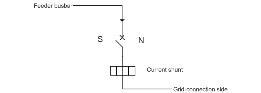
Below, we focus on how to simply verify, during operation & maintenance or commissioning of new lines, the accuracy of the polarity (N and S poles) of the arc-blowing coils (electromagnets) in DC incoming and outgoing feeder circuit breakers as set at the factory, ensuring an upward force is produced to pull the arc into the arc chute for correct and effective arc extinction.

I. DC Incoming Feeder Cabinet

How to determine the accuracy of the magnet polarity: the magnet on the left should be N-pole, and the one on the right should be S-pole.

As shown in the figure below: according to the left-hand rule, given the direction of current (I) and the direction of the Ampere force (F) acting on it (upward), the direction of the magnetic flux density (B)—which points from the N-pole—can be determined. Therefore, the magnet on the left side of the incoming feeder cabinet should be N-pole, and the one on the right should be S-pole.

image.png

Apply a millivolt-level voltage across the shunt to activate the magnetic blowout device. Then, bring a standard magnet (with known polarity) into contact with the magnets in the incoming feeder cabinet. Based on the principle that like poles repel and opposite poles attract, verify the correctness of the magnet polarity.

II. DC Outgoing Feeder Cabinet

How to determine the accuracy of the magnet polarity: the magnet on the left should be S-pole, and the one on the right should be N-pole.

As shown in the figure below: according to the left-hand rule, given the direction of current (I) and the direction of the Ampere force (F) acting on it (upward), the direction of the magnetic flux density (B)—which points from the N-pole—can be determined. Therefore, for the outgoing feeder cabinet, the magnet on the left should be S-pole, and the one on the right should be N-pole.

image.png

Apply a millivolt-level voltage across the shunt to activate the magnetic blowout device. Then, bring a standard magnet into contact with the magnet in the outgoing feeder cabinet. Based on the principle that like poles repel and opposite poles attract, verify the correctness of the polarity.

During routine maintenance, it is essential for personnel to master the use of the left-hand rule: given the direction of current and the Ampere force (F), determine the direction of the magnetic flux density (B), to verify whether the N and S pole orientation of the electromagnet is correct, ensuring accurate and effective arc extinction.

Give a tip and encourage the author!
Recommended
Hydraulic Leak & SF6 Gas Leakage in Circuit Breakers
Leakage in Hydraulic Operating MechanismsFor hydraulic mechanisms, leakage can cause short-term frequent pump starting or excessively long re-pressurization time. Severe internal oil seepage in valves may lead to pressure loss failure. If hydraulic oil enters the nitrogen side of the accumulator cylinder, it can cause abnormal pressure rise, which affects the safe operation of SF6 circuit breakers.Apart from failures caused by damaged or abnormal pressure detection devices and pressure component
Felix Spark
10/25/2025
10kV RMU Common Faults & Solutions Guide
1.Application Issues and Handling Measures for 10kV Ring Main Units (RMUs)The 10kV ring main unit (RMU) is a core power distribution device in urban 10kV distribution networks, widely used in industrial parks, residential communities, commercial centers, and public facilities for medium-voltage power supply and flexible power distribution. Its primary function is to enable flexible energy distribution, ring-fed operation, and fault isolation at the 10kV voltage level. However, during long-term o
Echo
10/20/2025
HV Breaker Fault Basics: Training Guide for New Engineers
High-Voltage Circuit Breakers: Classification and Fault DiagnosisHigh-voltage circuit breakers are critical protective devices in power systems. They rapidly interrupt current when a fault occurs, preventing damage to equipment from overloads or short circuits. However, due to long-term operation and other factors, circuit breakers may develop faults that require timely diagnosis and troubleshooting.I. Classification of High-Voltage Circuit Breakers1. By Installation Location: Indoor-type: Insta
Felix Spark
10/20/2025
10 Prohibitions for Transformer Installation and Operation!
10 Prohibitions for Transformer Installation and Operation! Never install the transformer too far away—avoid placing it in remote mountains or wilderness. Excessive distance not only wastes cables and increases line losses, but also makes management and maintenance difficult. Never choose transformer capacity arbitrarily. Selecting the right capacity is essential. If the capacity is too small, the transformer may be overloaded and easily damaged—overloading beyond 30% should not exceed two hours
James
10/20/2025
Send inquiry
Download
Get the IEE Business Application
Use the IEE-Business app to find equipment, obtain solutions, connect with experts, and participate in industry collaboration anytime, anywhere—fully supporting the development of your power projects and business.