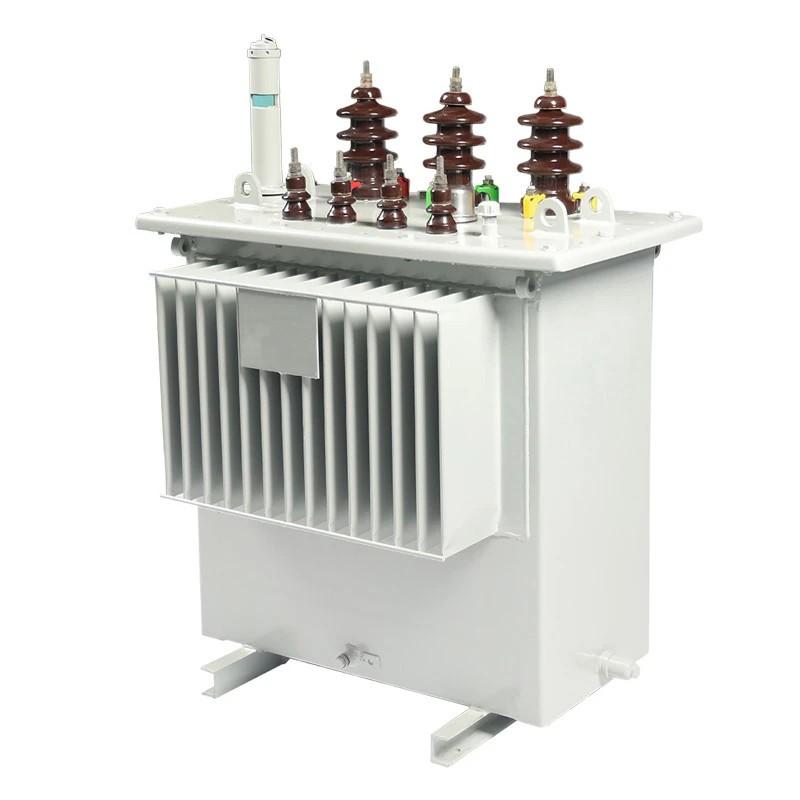
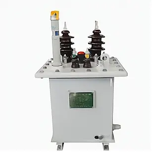
The Impact of Voltage Harmonics on Temperature Rise in H59 Distribution Transformers
H59 distribution transformers are among the most critical equipment in power systems, primarily functioning to convert high-voltage electricity from the power grid into low-voltage electricity required by end users. However, power systems contain numerous nonlinear loads and sources, which introduce voltage harmonics that adversely affect the operation of H59 distribution transformers. This article will discuss in detail the impact of voltage harmonics on the temperature rise of H59 distribution transformers.
First, we need to clarify what voltage harmonics are. Power sources, equipment, and nonlinear loads in electrical systems cause distortion in current and voltage waveforms, resulting in harmonic components beyond the fundamental frequency. Voltage harmonics refer to harmonic components in the voltage waveform whose frequencies are integer multiples of the fundamental frequency. Voltage harmonics lead to current harmonics, which in turn affect the normal operation of electrical equipment.
For H59 distribution transformers, voltage harmonics have several primary effects:
First, voltage harmonics increase transformer losses. Harmonic voltages cause additional iron losses and copper losses in the transformer, leading to higher temperature rise. The presence of harmonic voltages distorts the magnetic circuit of the transformer, resulting in non-uniform magnetic flux density distribution and increased iron losses. Additionally, harmonic currents flowing through the transformer windings produce extra resistive losses—i.e., increased copper losses. These additional losses are converted into heat, further raising the transformer’s temperature.
Second, voltage harmonics increase transformer noise. Electromagnetic forces in transformers result from changes in the magnetic field. Voltage harmonics make these magnetic field variations more complex, thereby intensifying mechanical vibrations and audible noise. This noise not only affects the transformer’s own operation but also causes acoustic pollution in the surrounding environment.

Furthermore, voltage harmonics may accelerate insulation aging in the transformer. Harmonic voltages cause uneven electric field distribution within the transformer’s insulation materials, creating regions of high electric field concentration. This leads to premature aging and degradation of the insulation. Such insulation aging increases the risk of transformer failure and may even cause partial discharge or dielectric breakdown.
To mitigate the impact of voltage harmonics on distribution transformers, the following measures can be adopted:
First, limit the use of nonlinear loads. Nonlinear loads are a major source of harmonics in power grids; reducing their usage effectively suppresses harmonic generation.
Second, install harmonic filters. Harmonic filters are electrical devices designed to eliminate harmonic currents, thereby reducing harmonic voltages. Using harmonic filters can significantly lessen the impact of voltage harmonics on transformers.
Third, increase the capacity of the distribution transformer. A larger transformer capacity reduces current density, thereby lowering both copper and iron losses and consequently reducing temperature rise.
Finally, perform regular maintenance and inspection of the transformer. Routine monitoring of temperature, noise, and other operational parameters allows timely detection of issues, enabling prompt maintenance and repair to ensure reliable operation and extend service life.
In summary, voltage harmonics have a significant impact on the temperature rise of H59 distribution transformers. They increase losses, elevate noise levels, and raise the risk of insulation aging. To reduce these adverse effects, measures such as limiting nonlinear loads, installing harmonic filters, increasing transformer capacity, and conducting regular maintenance can effectively minimize harmonic voltage levels. These actions help enhance the stability and reliability of distribution transformers and prolong their operational lifespan.