• Product
  • Suppliers
  • Manufacturers
  • Solutions
  • Free tools
  • Knowledges
  • Experts
  • Communities
Search


Motor Thermal Overload Protection

Encyclopedia
Encyclopedia
Field: Encyclopedia
0
China

Motor thermal overload protection set


Thermal overload protection is a safety mechanism that prevents the motor from overheating by detecting excessive current and stopping the motor.


Cause of overheating


When considering motor overheating, the first cause that comes to mind is overload. Mechanical overload causes the motor to consume a higher current, which leads to overheating. If the rotor is locked by external forces, consuming too much current, the motor will also overheat. Low supply voltage is another reason; The motor consumes more current to maintain torque. When one power supply phase fails, the single phase and the power supply are unbalanced, resulting in negative sequence current, which can also lead to overheating. When the motor accelerates to its rated speed, the sudden loss and recovery of voltage can lead to overheating, which consumes a large current.


Since thermal overload or overheating of the motor can lead to insulation failure and winding damage, for proper motor thermal overload protection, the motor should be protected from the following conditions


  • Mechanical overload

  • Motor shaft is blocked

  • Low supply voltage

  • Single-phase power supply

  • Power unbalance

  • Sudden loss and reconstruction of supply voltage


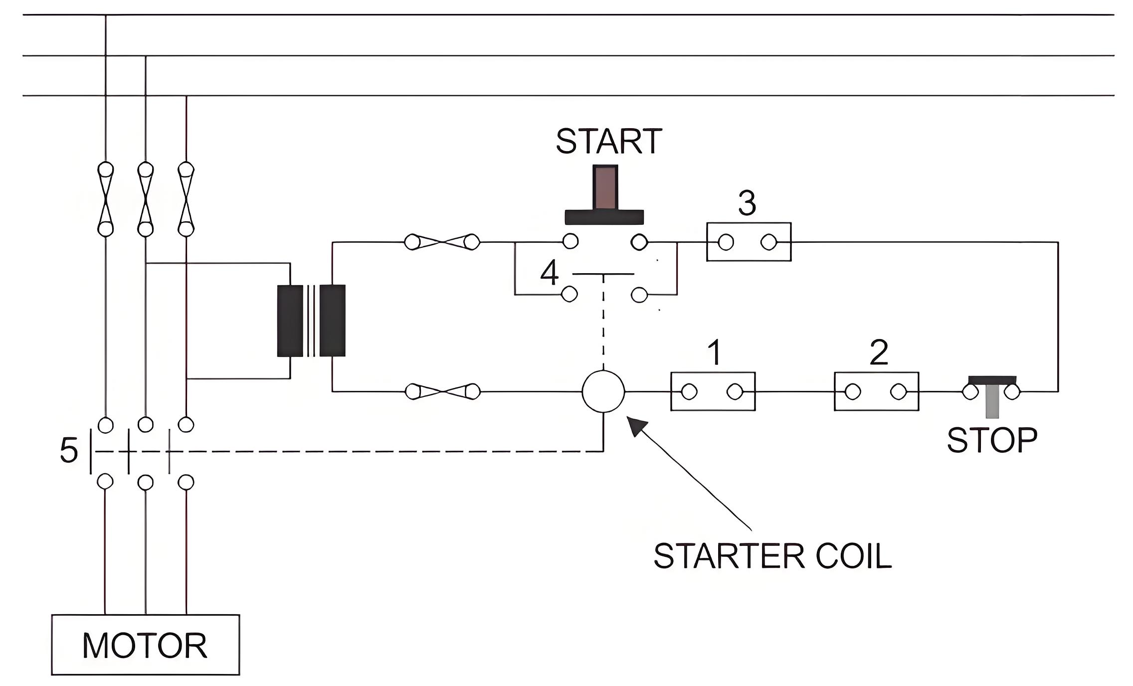
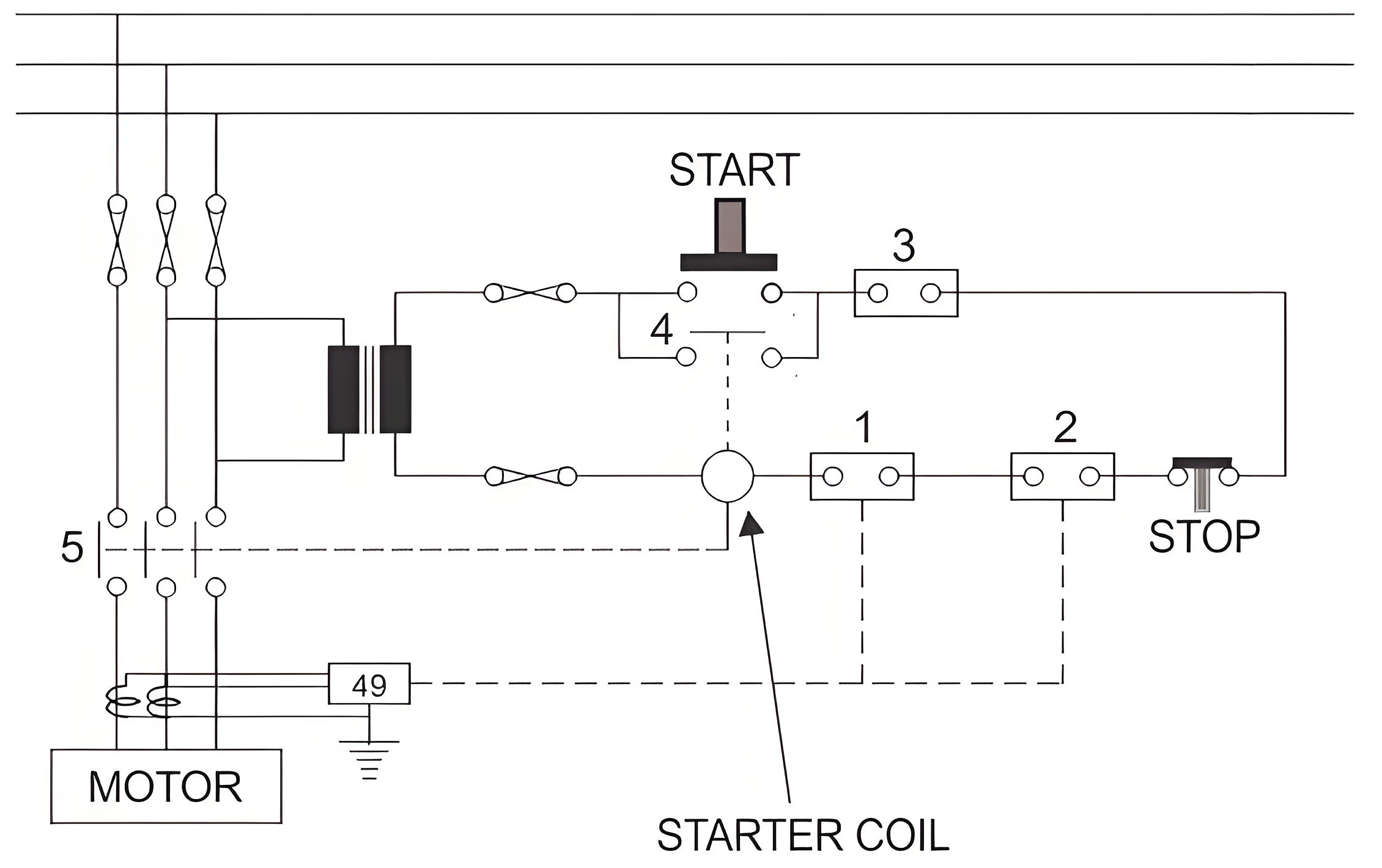
The most basic protection scheme of the motor is thermal overload protection, which mainly covers the protection of all the above situations. In order to understand the basic principle of thermal overload protection, let's look at the schematic diagram of the basic motor control scheme.


In the figure above, when the START push is closed, the start coil is energized through the transformer. When the starting coil is energized, the normally open (NO) contact 5 closes, so the motor obtains the supply voltage at its terminals and begins to rotate. The START coil also closes contact 4, energizing the start coil even if the Start button contact is released from its closed position.


 To stop the motor, there are several normally closed (NC) contacts in series with the starting coil, as shown in the figure. One of them is the STOP button contact. If the STOP button is pressed, this button contact will open and disconnect the continuity of the starting coil circuit, resulting in a power failure of the starting coil. 


Thus, contacts 5 and 4 return to their normal open positions. Then, in the absence of voltage at the motor terminals, it will eventually stop running. Similarly, any other NC contacts (1, 2, and 3), if opened, are connected in series with the starting coil; It will also stop the motor. These NC contacts are electrically coupled with various protective relays to stop the operation of the motor under different abnormal conditions


f37533a319f786320626fb5f0d1441af.jpeg


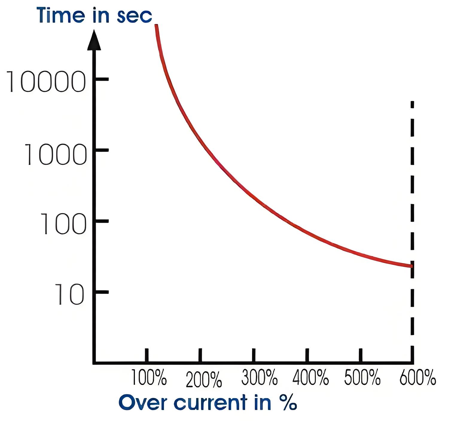
Another important point of motor thermal overload protection is the predetermined overload tolerance value of the motor. Each motor can operate for a period of time in excess of its rated load according to load conditions specified by the manufacturer. This relationship between motor load and safe operating time is shown in the thermal limit curve. Here is an example of such a curve.


Here the Y-axis or the vertical axis represents the allowable time in seconds, and the X-axis or the horizontal axis represents the overload percentage. It is clear from the curve that the motor can operate safely at 100% rated load for a long time without causing any damage due to overheating. It can operate safely for 1000 seconds at 200% of its normal rated load. It can operate safely for 100 seconds at 300% of normal rated load. 


It can operate safely for 600 seconds at 15% of its normal rated load. The top half of the curve indicates the normal operating conditions of the rotor, and the bottom half indicates the mechanical locking state of the rotor


3e74341d4f3d16ded26a8b6720277946.jpeg

7e07b7c9d6fe0766a1dd245ba3165ab2.jpeg

Thermal overload relay


The relay uses bimetal sheets that heat up and bend when the current is too high, breaking the circuit to stop the motor.


Thermal limiting curve


This curve shows how long the motor can operate at different overload levels without damage, helping to set protection limits.


RTD Advanced protection


Resistance temperature detectors (RTDS) provide precise motor protection by monitoring temperature changes and triggering protection measures.


Give a tip and encourage the author!
Recommended
What are the common faults encountered during the operation of power transformer longitudinal differential protection?
Transformer Longitudinal Differential Protection: Common Issues and SolutionsTransformer longitudinal differential protection is the most complex among all component differential protections. Misoperations occasionally occur during operation. According to 1997 statistics from the North China Power Grid for transformers rated 220 kV and above, there were 18 incorrect operations in total, of which 5 were due to longitudinal differential protection—accounting for approximately one-third. Causes of
Felix Spark
11/05/2025
Relay Protection Types in Substations: A Complete Guide
(1) Generator Protection:Generator protection covers: phase-to-phase short circuits in stator windings, stator ground faults, inter-turn short circuits in stator windings, external short circuits, symmetrical overload, stator overvoltage, single- and double-point grounding in the excitation circuit, and loss of excitation. Tripping actions include shutdown, islanding, limiting fault impact, and alarm signaling.(2) Transformer Protection:Power transformer protection includes: phase-to-phase short
Echo
11/05/2025
What Are the Factors Influencing the Impact of Lightning on 10kV Distribution Lines?
1. Induced Lightning OvervoltageInduced lightning overvoltage refers to the transient overvoltage generated on overhead distribution lines due to nearby lightning discharges, even when the line is not directly struck. When a lightning flash occurs in the vicinity, it induces a large amount of charge on the conductors—opposite in polarity to the charge in the thundercloud.Statistical data shows that lightning-related faults caused by induced overvoltages account for approximately 90% of total fau
Echo
11/03/2025
THD Measurement Error Standards for Power Systems
Error Tolerance of Total Harmonic Distortion (THD): A Comprehensive Analysis Based on Application Scenarios, Equipment Accuracy, and Industry StandardsThe acceptable error range for Total Harmonic Distortion (THD) must be evaluated based on specific application contexts, measurement equipment accuracy, and applicable industry standards. Below is a detailed analysis of key performance indicators in power systems, industrial equipment, and general measurement applications.1. Harmonic Error Standar
Edwiin
11/03/2025
Related Products
Send inquiry
Download
Get the IEE Business Application
Use the IEE-Business app to find equipment, obtain solutions, connect with experts, and participate in industry collaboration anytime, anywhere—fully supporting the development of your power projects and business.