Emergency Replacement Process of 40000 KVA Electric Arc Furnace Transformer in a Steel Plant

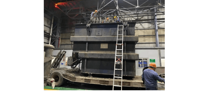
On the morning of January 1st at 9:00 AM, the Transformer Work Zone of the Electrical Maintenance Department received an emergency repair task: a 40,000 KVA electric arc furnace transformer at a steel plant had failed and needed replacement. As a critical piece of equipment in steelmaking, the furnace transformer directly impacts the output of upstream and downstream production lines. This replacement task was urgent, challenging, and technically demanding. Under the guidance and strong support of company leadership and relevant departments, the Transformer Work Zone united as one, overcame difficulties, and successfully completed the furnace transformer replacement.
The repair process involved multiple steps: removing and transporting the old transformer, returning the spare transformer to the workshop, disassembling it, conducting core lifting inspections, testing, reassembling, transporting it back to the site, and finally installing it. This series of operations required close collaboration among multiple work zones and specialized personnel, involving numerous staff and tools, as well as strict safety and quality controls.
The Transformer Work Zone meticulously organized the operation, establishing precise timelines for each step based on site conditions and available resources. Personnel and equipment for each process were prepared in advance to ensure seamless transitions between consecutive steps. While removing the faulty transformer, preparations for lifting and transportation were carried out simultaneously. During the removal of accessories and busbar bolts, personnel from the Ironmaking Maintenance Department were brought in to assist, while jigs for lifting and lateral movement of the transformer were fabricated in parallel, and the steel roof structure of the transformer room was pre-removed. Thanks to the concerted efforts of all involved work zones, the repair schedule was successfully maintained.
The leadership of the Electrical Maintenance Department placed high importance on this repair. They provided 24-hour on-site supervision, coordinated all necessary procedures, manpower, and materials, ensuring smooth organization throughout the repair process. The department currently has two specialized transformer teams with fewer than 20 personnel in total. From the start of the repair on January st to the commissioning of the new transformer on the 8th, maintenance staff worked around the clock in rotating shifts, strictly adhering to the repair schedule and successfully completing all tasks, demonstrating the tenacious spirit of a dedicated team.
The transformer unit itself weighs 70 tons and has numerous piping and fittings. The labor intensity during disassembly and installation was extremely high. The low-voltage side busbar connection alone has 864 bolts, arranged in tight rows with very small spacing. Power tools could not be used, and most bolts were inaccessible even with standard wrenches. The two teams alternated working on the transformer, four meters high, crouching for hours at a time.
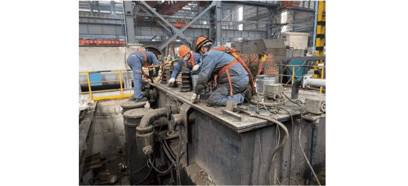
Removing the busbar connection bolts alone took an entire night. Since the spare transformer (originally scheduled for scrapping) had been in storage for many years, thorough inspection and testing were required to ensure reliability. During inspection, a fault was discovered in the tap changer: it failed to operate. Despite emergency assistance from the manufacturer, the root cause could not be resolved. To prevent the equipment from being put into service with hidden dangers, the transformer technical team decisively decided to disassemble the unit and perform a core lifting inspection. The inspection revealed a mechanical failure in the tap changer mechanism. The tap changer was manually adjusted to the fourth tap, allowing normal operation. Although the core inspection took an entire night, it successfully identified and eliminated the fault, giving the user confidence in the equipment’s reliability and fully demonstrating the technical strength of the transformer team.
The oil piping around the transformer body, porcelain insulators and copper busbars on top, and internal core and winding coils are all valuable and fragile components. During the removal, installation, transportation, and core lifting inspection, there could be no negligence or physical damage. The maintenance personnel handled each operation with craftsmanship, carefully confirming every component and step. After several days of continuous work, despite exhaustion, the team remained committed, maintaining high spirits and a strong sense of responsibility, ensuring that every process was completed with quality and precision.


