• Product
  • Suppliers
  • Manufacturers
  • Solutions
  • Free tools
  • Knowledges
  • Experts
  • Communities
Search


Working Principle and Characteristics of Rectifier Transformers

Ron
Ron
Field: Modeling and Simulation
Cameroon

Working Principle of Rectifier Transformers

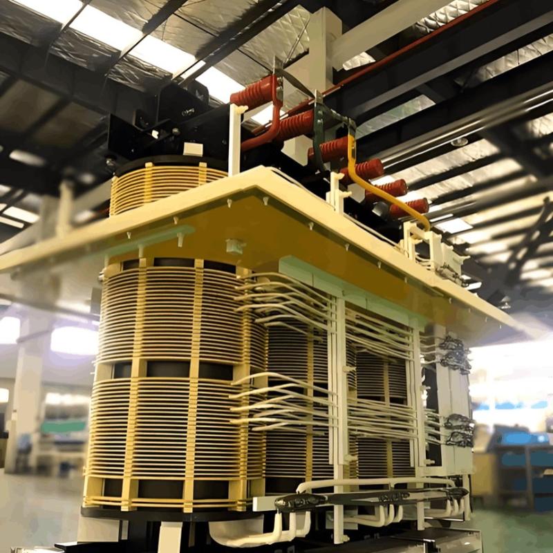
The working principle of a rectifier transformer is the same as that of a conventional transformer. A transformer is a device that converts AC voltage based on the principle of electromagnetic induction. Typically, a transformer consists of two electrically isolated windings—the primary and secondary—wound around a common iron core. When the primary winding is connected to an AC power source, the alternating current generates a magnetomotive force, producing a varying magnetic flux within the closed iron core. This changing flux links both windings, inducing an AC voltage of the same frequency in the secondary winding. The voltage ratio between the primary and secondary windings is equal to their turns ratio. For example, if the primary has 440 turns and the secondary has 220 turns with a 220 V input, the output voltage will be 110 V. Some transformers may have multiple secondary windings or taps to provide several output voltages.

Characteristics of Rectifier Transformers

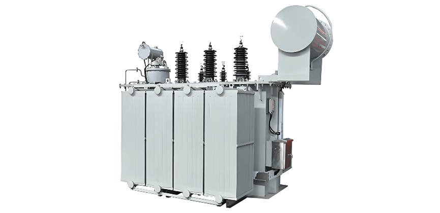
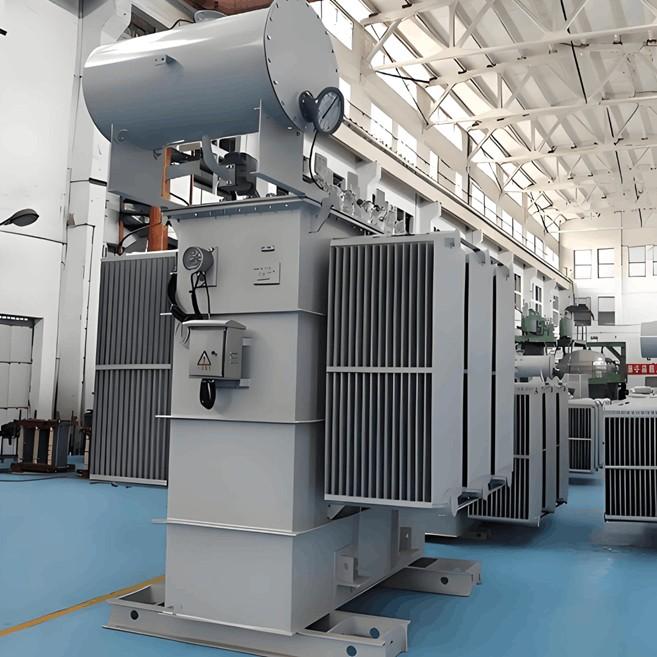
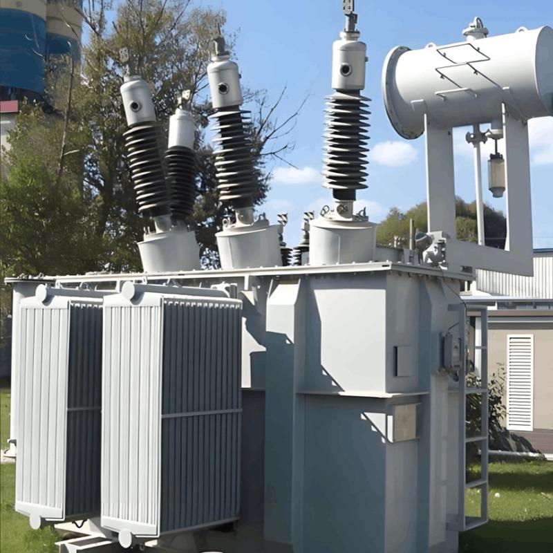
Rectifier transformers are used in conjunction with rectifiers to form rectifier systems, which convert AC power into DC power. These systems serve as the most common DC power sources in modern industrial applications and are widely used in areas such as HVDC transmission, electric traction, rolling mills, electroplating, and electrolysis.

The primary side of a rectifier transformer connects to the AC power grid (grid side), while the secondary side connects to the rectifier (valve side). Although the structural principle is similar to that of a standard transformer, the unique load—namely the rectifier—imparts specific characteristics:

  • Non-sinusoidal Current Waveforms: In a rectifier circuit, each arm conducts alternately during a cycle, with conduction time occupying only a portion of the cycle. As a result, the current waveform through the rectifier arms is not sinusoidal but resembles a discontinuous rectangular wave. Consequently, the current waveforms in both primary and secondary windings are non-sinusoidal. The figure illustrates the current waveform in a three-phase bridge rectifier with YN connection. When using thyristor rectifiers, a larger firing delay angle results in steeper current transitions and increased harmonic content, leading to higher eddy current losses. Since the secondary winding conducts only part of the cycle, the utilization of the rectifier transformer is reduced. Compared to conventional transformers, rectifier transformers are typically larger and heavier under the same power conditions.

  • Equivalent Power Rating: In a conventional transformer, the power on the primary and secondary sides is equal (neglecting losses), and the transformer's rated capacity corresponds to either winding's power. However, in a rectifier transformer, due to non-sinusoidal current waveforms, the primary and secondary apparent powers may differ (e.g., in half-wave rectification). Therefore, the transformer's capacity is defined as the average of the primary and secondary apparent powers, known as the equivalent capacity, given by S = (S₁ + S₂) / 2, where S₁ and S₂ are the apparent powers of the primary and secondary windings, respectively.

  • Short-Circuit Withstand Capability: Unlike general-purpose transformers, rectifier transformers must meet stringent requirements for mechanical strength under short-circuit conditions. Ensuring dynamic stability during short circuits is thus a critical consideration in their design and manufacturing.

Give a tip and encourage the author!
Recommended
Rectifier vs Power Transformer: Key Differences
Differences Between Rectifier Transformers and Power TransformersRectifier transformers and power transformers both belong to the transformer family, but they differ fundamentally in application and functional characteristics. The transformers commonly seen on utility poles are typically power transformers, while those supplying electrolytic cells or electroplating equipment in factories are usually rectifier transformers. Understanding their differences requires examining three aspects: working
Echo
10/27/2025
Rectifier Transformer: Working Principle & Applications
1.Rectifier Transformer: Principle and OverviewA rectifier transformer is a specialized transformer designed to supply rectifier systems. Its working principle is the same as that of a conventional transformer — it operates based on electromagnetic induction and is used to transform alternating voltage. A typical transformer has two electrically isolated windings — primary and secondary — wound around a common iron core.When the primary winding is connected to an AC power source, alternating cur
Echo
10/25/2025
How to Improve Rectifier Transformer Efficiency? Key Tips
Optimization Measures for Rectifier System EfficiencyRectifier systems involve numerous and diverse equipment, so many factors affect their efficiency. Therefore, a comprehensive approach is essential during design. Increase Transmission Voltage for Rectifier LoadsRectifier installations are high-power AC/DC conversion systems requiring substantial power. Transmission losses directly impact rectifier efficiency. Increasing the transmission voltage appropriately reduces line losses and improves r
James
10/22/2025
Transformer Common Faults Diagnostic Measures and Temperature Monitoring
1.Common Faults and Diagnostic Measures1.1 Transformer Oil Leakage1.1.1 Oil Leakage from Tank Weld SeamsFor oil leakage at flat joints, direct welding is applicable. For leakage at corners or joints reinforced with stiffeners, the exact leakage point is often difficult to locate, and re-leakage may occur after welding due to internal stress. For such cases, repair welding with an added iron plate is recommended: for two-surface joints, the iron plate can be cut into a spindle shape for welding;
Vziman
08/07/2025
Related Products
Send inquiry
Download
Get the IEE Business Application
Use the IEE-Business app to find equipment, obtain solutions, connect with experts, and participate in industry collaboration anytime, anywhere—fully supporting the development of your power projects and business.