What Are Key Circuit Breaker Mechanical Tests?

High-Voltage Circuit Breaker Characteristic Tests: Methods and Precautions
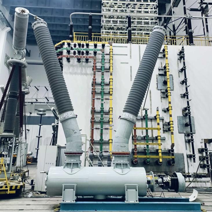
High-voltage circuit breaker characteristic tests are essential for verifying the mechanical integrity, electrical performance, and protective logic of switchgear. These tests include mechanical characteristics measurement, main loop resistance testing, anti-pumping function verification, and non-full-phase protection testing. Proper execution ensures reliable operation under normal and fault conditions.
1. Pre-Test Preparation
1.1 Technical Documentation Review
Thoroughly review the circuit breaker operating mechanism manual to understand its structure (spring, hydraulic, or electromagnetic), working principle, and key technical parameters such as rated operating voltage, opening/closing time, synchronization tolerance, contact travel, and overtravel.
Collect and analyze installation records, maintenance logs, and historical test reports to identify recurring issues or degradation trends (e.g., increasing contact resistance or closing bounce).
1.2 Equipment Preparation
Prepare the following calibrated instruments:
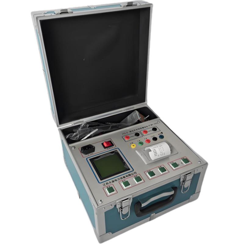
Circuit breaker mechanical characteristics tester (with timing, stroke, and speed measurement functions)
Micro-ohmmeter (capable of outputting ≥100A DC current)
Relay protection tester (for anti-pumping and non-full-phase logic verification)
Displacement sensors (linear variable differential transformer – LVDT or rotary encoder), voltage probes, and connection cables
Ensure all test equipment has valid calibration certificates and meets accuracy requirements (e.g., ±0.1ms for timing, ±1% for resistance).
1.3 Safety Measures
Disconnect control power, energy storage power, and secondary wiring before starting work.
Release stored energy in the operating mechanism—fully discharge closing and opening springs; depressurize hydraulic systems.
Personnel must wear appropriate personal protective equipment (PPE): insulated gloves, safety goggles, arc-flash clothing, and hard hats.
Erect warning signs and barriers around the test area to prevent unauthorized access.
Ensure reliable grounding of the circuit breaker frame, test equipment, and surrounding metal structures to eliminate risks from induced voltages or leakage currents.
2. Mechanical Characteristics Test
2.1 Opening/Closing Time Measurement
Install displacement sensors on the moving contact rod or use auxiliary switch contacts to capture motion signals. Apply rated control voltage (DC 110V/220V) and rated operating pressure (if applicable). Operate the breaker and record the time from command initiation to complete separation (opening time) or full engagement (closing time).
Perform at least three consecutive operations under identical conditions, calculate the average, and compare with manufacturer specifications. Significant deviations may indicate sluggish solenoids, low spring energy, or mechanical binding.
2.2 Synchronization Check
Measure the time difference between the first and last phase to separate during opening (phase-to-phase opening synchronization) and the same for closing. For high-voltage breakers (≥72.5kV), synchronization error should typically be ≤3ms; for lower voltages, ≤5ms is acceptable.
In multi-break per phase designs, inter-pole synchronization within a single phase must be even tighter (≤1–2ms).
If out of tolerance, inspect consistency in linkage lengths, pivot alignment, buffer settings, or gas/hydraulic pressures.
2.3 Contact Travel and Overtravel Measurement
Use the mechanical tester’s stroke channel to directly measure total contact travel and overtravel (the distance the contact moves after initial touch during closing). Alternatively, infer values from linkage displacement using geometric conversion.
Values must comply with factory specifications. Insufficient overtravel reduces contact pressure and increases resistance; excessive overtravel may cause mechanical stress. Adjust via insulating pull rod length or mechanism positioning.
2.4 Opening/Closing Speed Measurement
Speed is critical for arc extinction capability. Measure:
Just-open speed: average speed over 6–10mm after contact separation
Just-closed speed: average speed over same distance before final contact
Maximum speed during stroke
Results should fall within specified ranges. Low just-open speed may lead to inadequate dielectric recovery; high just-closed speed increases bounce risk. Abnormalities often stem from worn buffers, degraded springs, or incorrect lubrication.
2.5 Closing Bounce Time Measurement (Applicable to Vacuum Circuit Breakers)
During closing, temporary loss of contact due to rebound is measured as closing bounce time—the interval from first contact to stable engagement. It should generally be ≤2ms.
Excessive bounce causes pre-arcing, leading to contact erosion and potential welding. Causes include weak contact springs, worn linkages, or improper damping. Verify spring force and adjust buffer characteristics if necessary.
3. Loop Resistance Test
3.1 Define Conductive Path
Identify the entire main current path: line terminal → fixed contact → moving contact → moving conductive rod → soft connection → load terminal. This forms the "loop" for resistance measurement.
3.2 Clean Test Points
Remove oxidation, paint, grease, or contamination from contact surfaces and terminal clamps using fine sandpaper or conductive cleaning compound. Poor surface condition leads to false high readings.
3.3 Measure Loop Resistance
Apply a constant DC current (typically 100A or 200A) through the main circuit using a micro-ohmmeter. Measure the voltage drop across the contacts and calculate resistance using Ohm’s Law (R = V/I).
Typical values range from 20μΩ to 200μΩ, depending on voltage class and design. A result exceeding the initial value by more than 20%, or above the manufacturer's limit, indicates poor contact pressure, loose connections, or contact degradation—requiring inspection or replacement.
4. Anti-Pumping (Trip-Lockout) Function Test
4.1 Test Method
The anti-pumping relay prevents repeated closing attempts during a persistent close command (e.g., stuck button or faulty control circuit), which could damage the breaker during an external fault.
Case 1: With the breaker closed, simultaneously apply close and trip commands. The breaker should trip once and remain open—the anti-pumping relay must block any subsequent close operation.
Case 2: With the breaker open, apply both commands together. The breaker should close momentarily and then immediately trip, ending in the open position without re-closing.
4.2 Function Verification
Observe the status of the anti-pumping relay and auxiliary contacts. If only one trip occurs and the closing circuit is reliably locked out, the function is normal.
If “pumping” (repeated closing/tripping) occurs, check:
Relay coil energization and latching behavior
Auxiliary contact condition (burning, sticking)
Wiring continuity and insulation integrity
5. Post-Test Procedures
5.1 Data Recording and Analysis
Record all test results clearly, including:
Date, ambient temperature, operator name
Measured values vs. specification limits
Waveforms (timing, stroke, speed)
Compare with baseline data and previous results. Investigate any significant deviation (>10%) to determine root cause—mechanical wear, misadjustment, or component failure—and perform corrective actions accordingly.
5.2 Restore Equipment
After testing:
Remove all sensors, test leads, and clamps.
Return the breaker to its original operational state (open or closed as required).
Reconnect control and energy storage circuits.
Confirm no tools or foreign objects remain inside the compartment.
Only return the equipment to service after a final visual inspection and clearance from the test supervisor.
6. Key Precautions
Prohibit unauthorized operation of the breaker or test equipment during testing to prevent misoperation, mechanical injury, or electric shock.
Securely install sensors—loose mounting can cause signal loss or inaccurate stroke/speed readings.
For breakers equipped with dual trip coils (Trip Coil 1 and Trip Coil 2), perform independent mechanical characteristic tests for each coil to verify consistent tripping performance.
Conduct insulation withstand (hi-pot) tests before and after characteristic testing to confirm dielectric strength integrity, especially after internal inspection or component replacement.
Avoid performing mechanical tests at extremely low temperatures (<−10°C), as cold weather affects lubricant viscosity and spring performance.
Always follow the manufacturer’s commissioning and maintenance guidelines—modifications or non-standard adjustments may void warranties or compromise safety.