1 Characteristics and Components of High-Voltage Transmission Lines
1.1 Characteristics of High-Voltage Transmission Lines
High-voltage transmission lines are characterized by their relatively low cost due to the smaller amount of information they require. They typically use two conductors, one connected to the positive pole and the other to the negative pole. DC transmission lines have durability and can transmit current over long distances. In some high-voltage transmission facilities in China, AC transmission is also widely used, which is particularly evident in daily life.
1.2 High-Voltage Transmission Lines as a Major Component of Electrical Design
In basic design work, engineering drawings required for construction must be carefully prepared and followed according to the work procedures. The selection of raw materials for construction plans, as well as the reasonable design of construction routes, methods, and corresponding storage challenges by the construction team, ensure the normal operation of power lines, improve work efficiency, and enhance the effectiveness of construction work.
2 Development Status of Ultra-High Voltage Transmission Lines
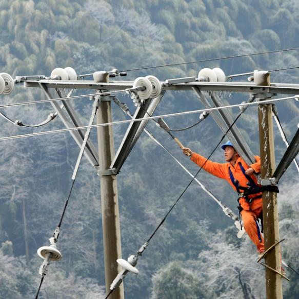
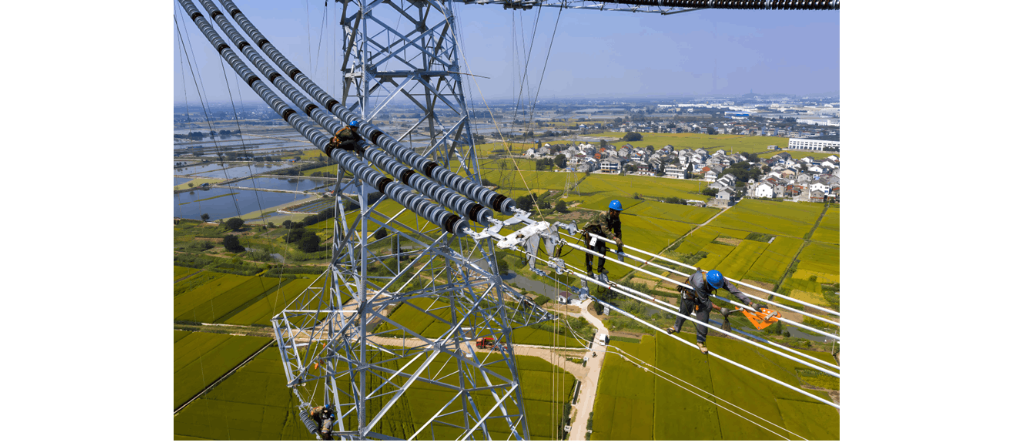
Compared with ordinary lines, ultra-high voltage (UHV) lines have higher requirements, such as external line insulation levels, power engineering technologies, and line protection measures. If the external insulation level of UHV transmission lines is not up to standard or protective measures are insufficient, faults such as pollution flashover, overvoltage, and breakdown will increase. Therefore, using composite insulators on UHV transmission lines is essential and an indispensable part of modern grid construction.
3 Problems with Composite Insulators in UHV Transmission Lines
3.1 Interface Breakdown
The electrical damage problems of composite insulators are mainly caused by lightning strikes, accounting for more than half of all damages. Although materials are continuously improving, the issue of repeated interface damage still exists. During production, both core rods and sheaths exhibit significant shedding phenomena, and the interfaces of sheaths and rod diameters may be eroded, potentially leading to interface damage and affecting the service life of insulators. Continuous optimization and improvement of products are necessary to reduce the probability of interface failure.
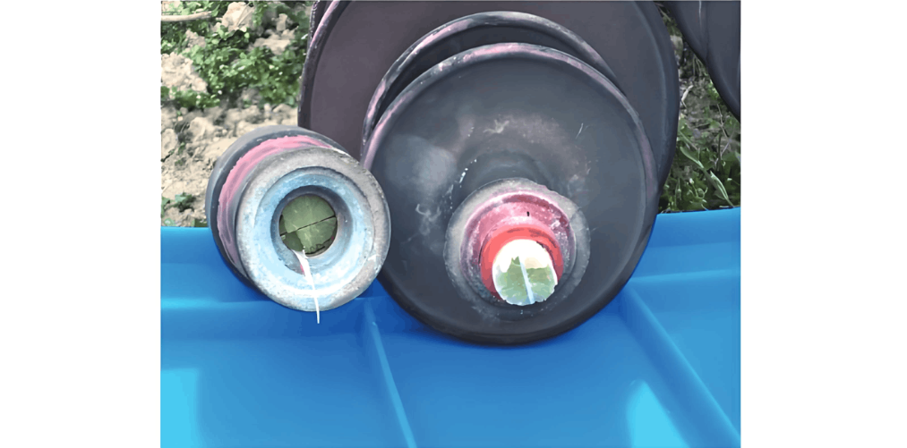
3.2 Core Rod Brittle Fracture
Core rod brittle fracture is a common type of composite insulator fault frequently encountered in UHV transmission lines. During the process of core rod brittle fracture, due to acid erosion, the core rod fibers gradually break under the action of acid erosion, even causing the entire core rod to fracture under small loads. The main reasons are as follows:
Firstly, it usually occurs at positions where the terminal field strength of high voltage is relatively high. Reversing the grading ring can lead to the brittle fracture of composite material insulators. To solve this problem, the design and processing of grading rings should ensure that the magnetic field strength reaches the specified level, effectively avoiding material brittle fracture.
Secondly, cracks may occur when the sheath or end face is damaged. However, using new boron-free fiber acid-resistant core rods significantly improves overall acid resistance, greatly reducing this issue. It is worth noting that not all fiber core rods possess excellent acid resistance characteristics; therefore, performance evaluation and selection are necessary. Although brittle fractures have a significant impact on operations, their occurrence probability is low and can be reduced through various interventions.
3.3 Aging Issues
After a period of use, insulators may experience aging problems primarily caused by temperature and surface discharge factors. Although silicone rubber materials have a longer aging cycle, early-stage operational aging can still occur due to environmental pollution and material formulation technology. While most regions can maintain good conditions and characteristics through silicone gel, aging is inevitable. To ensure the safe operation of insulators, early testing is necessary. Therefore, periodic inspections of composite material insulators are required to prevent further deterioration.
3.4 Mechanical Issues
Composite material insulators exhibit significant mechanical performance degradation during use. Currently, internal plug-type insulators are used, but they have high requirements for jointing methods, with significant differences in creep slope compared to edge-rolled insulator designs.
4 Determination of Insulator String Length and Minimum Air Gap Distance for UHV Lines
4.1 Electrical Insulation Distance Considered in UHV Line Design
The insulation matching requirements for 1000kV AC UHV lines must ensure safe and reliable operation under various conditions such as power frequency, switching overvoltage, and lightning overvoltage. The power frequency flashover of insulators is the primary control factor for insulator strings. External insulation structures are typically calculated based on pollution tolerance, combined with existing engineering experience, considering factors like altitude and ice coverage. For switching overvoltage, overvoltage multiples of 1.6p.u. and 1.7p.u. are taken; when the system's highest operating voltage is 1100kV, if the switching overvoltage cannot control the number of insulator pieces and the calculated value is lower than 50% of the insulator string's impulse discharge voltage, there is a risk of impulse discharge. In UHV systems, lightning overvoltage has no direct relationship with operating voltage, and the high external insulation level makes lightning overvoltage a non-determining factor.
4.2 Insulator String Length
Under polluted conditions, the length of the insulator string is determined using anti-pollution methods. This includes: (1) measuring the pollution flashover voltage of different insulators under atmospheric conditions to obtain the relationship between the 50% pollution flashover voltage and salt density of different insulators; (2) measuring the withstand voltage of insulators; (3) correcting and calculating the salt density of soluble salts; (4) calibrating the effect of ash-to-salt ratio on the surface contamination of insulators; (5) correcting the unevenness of the upper and lower surfaces; (6) performing elevation correction at high altitudes; and (7) calculating the number of insulator sections under maximum working voltage conditions.
4.3 Determination of Minimum Air Gap Distance for UHV Lines
4.3.1 Calculation of Minimum Number of Insulator Pieces for Normal Operation
This paper focuses on the key scientific issue of selecting the minimum clearance for UHV transmission lines, using single-circuit transmission lines as the research object. It studies the influence of air gap distance on transmission tower dimensions under power frequency voltage and lightning effects, determines the minimum clearance of transmission towers using measured air gap distances, and considers the impact of insulator degradation on transmission tower structures, proposing a minimum clearance for transmission towers considering insulator degradation.
4.3.2 Determination of Switching Overvoltage Gap
This involves determining the statistical matching factor for switching overvoltage operation based on the calculation of the working pulse discharge voltage U50% for individual air gaps.

Among these, Us represents the switching overvoltage, measured in kV; Z is a constant, thus it is set to 2.45; for a single air gap, σ1 is set to 0.06; among these,σm is the variance of multiple air gaps, which is set to 0.024. Therefore:
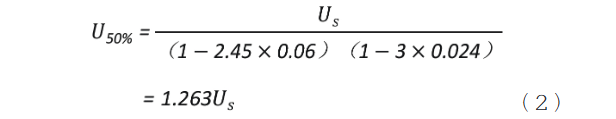
Therefore, the statistical coordination factor kc for the operating overvoltage of the line air gap is:

5 Application of Composite Insulators in Ultra-High Voltage Transmission Lines
Through practical operations of existing lines in our country, it has been found that using composite insulators can reduce both line maintenance costs and pollution to the power grid. In polluted areas, it is recommended to use composite insulators. For 1000kV transmission lines, it is recommended to use insulators about 9 meters high, and in heavily polluted areas, insulators over 17 meters high. If multiple series connections are adopted, the height of the insulators can be further adjusted, but this will also increase the weight and length of the insulators, raising the cost of the line.
In high-altitude and heavily polluted areas, composite insulators offer higher economic and technical advantages. When the combined string length does not exceed 10 meters, it can reduce the tower window area, control the tower load, and decrease the occurrence of flashover accidents. Therefore, composite material insulators have significant advantages in these aspects.To ensure the long-term stable and reliable operation of ultra-high voltage transmission lines, in-depth research must be conducted.
On one hand, studies on the mechanical properties of ultra-large-tonnage composite material insulators should be carried out to form efficient standards and testing methods. Additionally, while ensuring uniform pressure on composite insulators, appropriate measures should be taken to address electromagnetic interference and corona discharge issues to minimize sudden accidents. A reasonable arcing method ensures effective arc suppression.
Optimized mechanical structures guarantee that a broken insulator will not fall to the ground. Strict quality control standards should be established to prohibit substandard products, with strict material control for core rods and skirts, and improvements in manufacturing techniques from the source to reduce operational safety hazards. During construction, a scientific storage procedure should be implemented to strictly control potential damages. Effective maintenance and inspection plans should be executed to promptly identify safety hazards and take corresponding measures to ensure production safety.
6 Conclusion
Composite insulators have gained increasing application in China's power grid and have become an essential component of power grid construction. Given the requirements for large cross-sectional areas and high-load conditions in ultra-high voltage transmission lines, synthetic insulators should be prioritized over glass insulators and other types. As the scale of ultra-high voltage transmission lines expands, more challenges arise, leading to higher demands on their performance.
Besides ensuring uniform pressure on composite insulators, appropriate measures should be taken to address electromagnetic interference and corona discharge issues to minimize sudden accidents. A reasonable arcing method ensures effective arc suppression. Optimized mechanical structures guarantee that a broken insulator will not fall to the ground. Strict quality control standards should be established to prohibit substandard products, with strict material control for core rods and skirts, and improvements in manufacturing techniques from the source to reduce operational safety hazards.
During construction, a scientific storage procedure should be implemented to strictly control potential damages. Effective maintenance and inspection plans should be executed to promptly identify safety hazards and take corresponding measures to ensure production safety.