Application Analysis of Load Switch and Current-Limiting Fuse Combination Apparatus

As a front - line technician in loop - network power supply and prefabricated substation operation and maintenance, I deeply understand equipment iteration driven by high - voltage urban expansion. Per the National Power Supply and Consumption Regulations, for equipment over 250kW or 160kVA transmission capacity, 10(6)kV high - voltage power supply and 220/380V step - down form a necessary pattern, making loop - network units and prefabricated substations key in distribution networks.
I. Equipment Structure and Protection Scheme Selection
(I) Equipment Composition
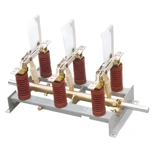
Loop - network units I handle usually have 2 loop cable intervals and 1 transformer circuit interval. Prefabricated substations integrate high - voltage switches, transformers, and low - voltage devices into compact, prefabricated sets for indoor/outdoor use. The core is high - voltage switches’ protection against transformer faults (e.g., short circuits).
(II) Protection Scheme Comparison
In practice, I tested two protection methods: circuit breaker and load switch + current - limiting fuse. The latter is superior —— simple, cost - effective, and more effective for transformers. Short - circuit tests show transformers need short - circuit clearing within 20ms to avoid tank explosions; current - limiting fuses do it in 10ms, while circuit breakers take ~60ms (relay + operation + arcing time), so I prefer the fuse scheme.
II. Necessity of Load Switch + Current - Limiting Fuse
(I) Application Advantages
Most domestic and foreign loop - network/prefabricated substation projects I participated in use load switch + current - limiting fuses. They feature simple structure, low cost, and good protection for transformers. Short - circuit tests (verified on - site) show fuses clear faults in 10ms (vs. circuit breakers’ ~60ms), critical for preventing tank explosions.
(II) Cooperative Logic
Fuses may cause unbalanced phase operation if single - phase fusing occurs. Thus, load switches must cooperate: fuse strikers trigger load switch tripping for three - phase breaking —— a verified, indispensable coordination.
III. Cooperation Key Points of Load Switch and Fuse
As a front - line worker, I know their cooperation is vital. The IEC420 standard defines rules, dividing current into 4 regions (my debugging basis):
(I) Region I (I < Iak)
Iak (combined appliance rated current) is less than fuse rated current Ia.nT (due to installation temperature/heat loss). Load switches break rated current and extinguish three - phase arcs —— my daily inspection focus.
(II) Region II (Ia.nT< I < 3Ia.nT)
In overload, fuses bear over - current first. At ~2Ia.nT, melts act (but not arc - extinguishing), strikers trigger load switches for three - phase breaking. I test this time - difference logic to avoid protection failure.
(III) Region III (Transfer Current ITC, ~3Ia.nT Start)
Fuses can extinguish arcs after action. One three - phase fuse acts first, triggering strikers; load switches extinguish other two - phase currents. The key is transfer current (load switch’s max breaking current at specific power factor, 5Ia.nT - 15Ia.nT), checked during selection/verification.
(IV) Region IV (Current - Limiting Range)
For extreme faults, fuses act in the first half - wave to limit fault current peaks; load switches act but don’t break current. I verify this logic in drills for proper operation.
IV. Transfer & Hand - over Current Requirements
These parameters ensure equipment safety, key for my on - site debugging:
(I) Transfer Current
It’s the critical value for function transfer between fuses and load switches. Below it, fuses break one phase, load switches handle the rest. Striker - equipped load switches need transfer current tests (usually > rated current) —— a challenge for old equipment, verified per IEC420.
(II) Hand - over Current
It’s the current fully broken by load switches (no fuse participation). For load switches with both strikers and releases, hand - over current tests are needed. If hand - over current > transfer current, transfer tests may be exempt. Release operation reduces fuse loss but increases vacuum load switch costs (adding relays/releases) —— trade - offs made per project budgets/conditions.
V. Transformer Protection Suggestions
For load switch + fuse transformer protection, key verifications include:
These tasks are mandatory for new projects/old equipment transformations. As a front - line worker, I ensure stable power supply and safe fault handling for downstream users.