• Product
  • Suppliers
  • Manufacturers
  • Solutions
  • Free tools
  • Knowledges
  • Experts
  • Communities
Search


What are the common faults of load switches?

Felix Spark
Felix Spark
Field: Failure and maintenance
China

As an on-site maintenance technician, I frequently deal with electrical, mechanical, and insulation faults in load switches. The following outlines fault manifestations, causes, and solutions:

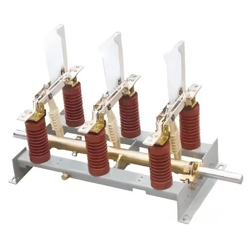
I. Electrical Fault Handling
(1) Contact Heating

Contact heating is mainly caused by poor contact, insufficient pressure, or three-phase asynchrony. When the contact resistance exceeds 1.5 times the initial value, the temperature rise will exceed the standard in a 40℃ environment. For example, the FW4-10 switch only has an electrical life of 5 times when breaking an 800A current.

Solutions:

  • Clean silver contacts with 25%-28% ammonia water, then apply neutral Vaseline.

  • Adjust main contact pressure to ≥150N.

  • Calibrate opening/closing synchronism to ≤3.3ms/≤5ms.

(2) Fuse Blowing

Fuse blowing results from short circuits, overloads, or improper selection (e.g., RN1-10 fuses rated 2-5000A). Replace fuses after identifying the cause, and ensure the load switch can handle currents within the "transfer current" range.

(3) Abnormal Arcing

Arcing issues stem from failed arc extinguishers or degraded contact materials. Regularly inspect the arc chamber and cylinder seals in pneumatic switches, and avoid frequent high-current operations per GB/T 3804.

II. Mechanical Fault Handling
(1) Operating Mechanism Jamming

Jamming occurs due to component aging, insufficient lubrication, etc. Detect jamming via motor current analysis, then:

  • Check connecting rod torque (M10 bolt 8.8 grade → 20±2N·m).

  • Apply molybdenum disulfide grease (drop point ≥300℃).

  • Replace fatigued springs and adjust the spindle angle/crank arm.

(2) Contact Wear

Wear is caused by frequent operations and arcing. Replace CuW80 contacts if wear exceeds 3mm. Monitor wear regularly and maintain synchronism (opening ≤3.3ms, closing ≤5ms) to balance three-phase currents.


(3) Interlock Failure

Interlock failure, often from mechanical wear, poses safety risks. Regularly inspect interlock structures and test functions, replacing components as needed.

III. Insulation Fault Handling
(1) Insulation Moisture

Moisture ingress occurs in high-humidity environments (e.g., coastal areas). Use EPDM seals and:

  • Dry and apply nano moisture-proof coatings.

  • Replace insulation parts or oil (ensure breakdown voltage ≥25kV for oil-immersed switches).

(2) Insulation Aging

Aging accelerates at high temperatures (10℃ rise shortens life by 50%-70%). Monitor via tanδ, insulation resistance, and partial discharge (PD ≤10pC). Replace aged parts and use CT scans for epoxy components.

(3) Insulation Resistance Drop

Test with a 2500V megohmmeter (≥1000MΩ). Investigate drops via oil analysis and replace/repair faulty parts.

Give a tip and encourage the author!
Recommended
Hydraulic Leak & SF6 Gas Leakage in Circuit Breakers
Leakage in Hydraulic Operating MechanismsFor hydraulic mechanisms, leakage can cause short-term frequent pump starting or excessively long re-pressurization time. Severe internal oil seepage in valves may lead to pressure loss failure. If hydraulic oil enters the nitrogen side of the accumulator cylinder, it can cause abnormal pressure rise, which affects the safe operation of SF6 circuit breakers.Apart from failures caused by damaged or abnormal pressure detection devices and pressure component
Felix Spark
10/25/2025
10kV RMU Common Faults & Solutions Guide
1.Application Issues and Handling Measures for 10kV Ring Main Units (RMUs)The 10kV ring main unit (RMU) is a core power distribution device in urban 10kV distribution networks, widely used in industrial parks, residential communities, commercial centers, and public facilities for medium-voltage power supply and flexible power distribution. Its primary function is to enable flexible energy distribution, ring-fed operation, and fault isolation at the 10kV voltage level. However, during long-term o
Echo
10/20/2025
HV Breaker Fault Basics: Training Guide for New Engineers
High-Voltage Circuit Breakers: Classification and Fault DiagnosisHigh-voltage circuit breakers are critical protective devices in power systems. They rapidly interrupt current when a fault occurs, preventing damage to equipment from overloads or short circuits. However, due to long-term operation and other factors, circuit breakers may develop faults that require timely diagnosis and troubleshooting.I. Classification of High-Voltage Circuit Breakers1. By Installation Location: Indoor-type: Insta
Felix Spark
10/20/2025
10 Prohibitions for Transformer Installation and Operation!
10 Prohibitions for Transformer Installation and Operation! Never install the transformer too far away—avoid placing it in remote mountains or wilderness. Excessive distance not only wastes cables and increases line losses, but also makes management and maintenance difficult. Never choose transformer capacity arbitrarily. Selecting the right capacity is essential. If the capacity is too small, the transformer may be overloaded and easily damaged—overloading beyond 30% should not exceed two hours
James
10/20/2025
Send inquiry
Download
Get the IEE Business Application
Use the IEE-Business app to find equipment, obtain solutions, connect with experts, and participate in industry collaboration anytime, anywhere—fully supporting the development of your power projects and business.