• Product
  • Suppliers
  • Manufacturers
  • Solutions
  • Free tools
  • Knowledges
  • Experts
  • Communities
Search


Permanent Magnet Stepper Motor

Encyclopedia
Encyclopedia
Field: Encyclopedia
0
China

The permanent magnet stepper motor features a stator construction that closely resembles that of the single - stack variable reluctance motor. Its rotor, cylindrical in shape, is composed of permanent magnet poles made from high - retentivity steel. On the stator, the concentrating windings situated on diametrically opposite poles are connected in series, thereby forming a two - phase winding.

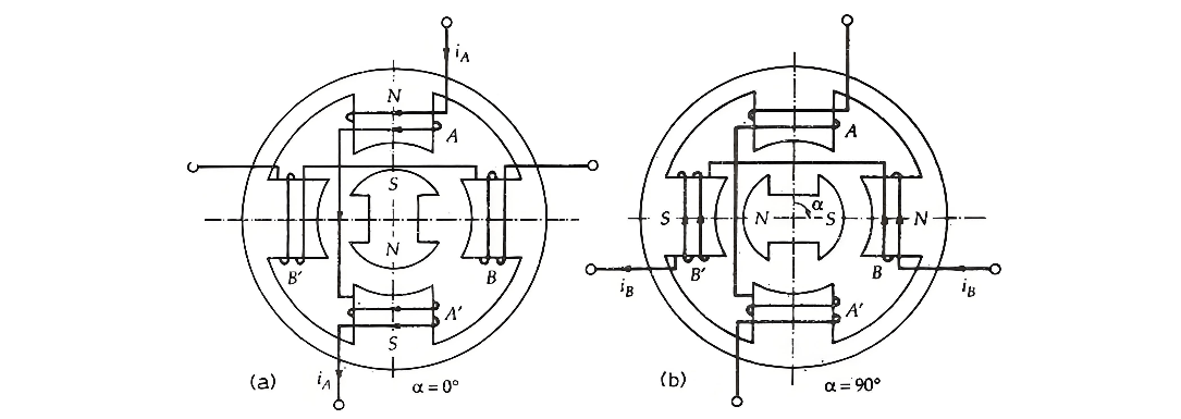
The alignment of the rotor poles with the stator teeth is contingent upon the excitation of the winding. For instance, the two coils AA’ are connected in series to constitute a winding for Phase A. Likewise, the two coils BB’ are connected in series to create a Phase B winding. The diagram below illustrates a 4/2 - pole permanent magnet stepper motor, providing a visual representation of its structural and winding configuration.

image.png

In Figure (a), the current flows from the start to the end of Phase A. The phase winding is labeled as A, and the current is denoted by iA+. This figure depicts the scenario when the phase winding is energized with the current iA+. As a result, the south pole of the rotor is attracted by Stator Phase A. Consequently, the magnetic axes of the stator and rotor align perfectly, with the angular displacement α=0∘.

Similarly, in Figure (b), the current traverses from the start to the end of Phase B. The current is indicated as iB+, and the winding is marked as B. When examining Figure (b), it can be observed that the winding of Phase A carries no current, while Phase B is excited by the current iB+. The stator pole then attracts the corresponding rotor pole, causing the rotor to rotate 90 degrees in the clockwise direction. At this stage, α=90∘.

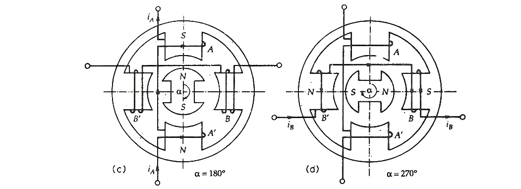
Figure (c) illustrates a situation where the current flows from the end to the start of Phase A. This current is represented by iA−, and the winding is labeled as iA−. Notably, the current iA− has a direction opposite to that of iA+. In this case, the Phase B winding is de - energized, and the Phase A winding is activated by the current iA−. Consequently, the rotor continues to move another 90 degrees in the clockwise direction, and the angular displacement reaches α=180∘.

image.png

In Figure (d) above, the current flows from the end to the starting point of Phase B, denoted as iB−, and the corresponding winding is labeled B−. At this moment, Phase A is de - energized, while Phase B is excited. As a result, the rotor advances another 90 degrees, and the angular displacement α reaches  270∘.

To complete a full revolution of the rotor, achieving α=360∘, the rotor moves an additional 90 degrees when the winding of Phase B is de - energized and Phase A is excited. In a permanent magnet stepper motor, the direction of rotation is determined by the polarity of the phase current. For clockwise rotation, the sequence of phase excitation is A,B,A−,B−,A, while for counterclockwise rotation, the sequence becomes A,B−,A−,B,A.

Manufacturing a permanent magnet rotor with a large number of poles presents significant challenges. Consequently, this type of stepper motor is typically limited to large step sizes, ranging from 30∘ to 90∘. These motors have higher inertia, which results in a lower acceleration rate compared to variable reluctance stepper motors. However, they possess an advantage in that permanent magnet stepper motors can generate greater torque than variable reluctance stepper motors.

Give a tip and encourage the author!
Recommended
SST Technology: Full-Scenario Analysis in Power Generation, Transmission, Distribution, and Consumption
I. Research BackgroundPower System Transformation NeedsChanges in energy structure are placing higher demands on power systems. Traditional power systems are transitioning toward new-generation power systems, with the core differences between them outlined as follows: Dimension Traditional Power System New-Type Power System Technical Foundation Form Mechanical Electromagnetic System Dominated by Synchronous Machines and Power Electronic Equipment Generation-Side Form M
Echo
10/28/2025
SST Transformer Core Loss Calculation and Winding Optimization Guide
SST High-Frequency Isolated Transformer Core Design and Calculation Material Characteristics Impact:Core material exhibits varying loss behavior under different temperatures, frequencies, and flux densities. These characteristics form the foundation of overall core loss and require precise understanding of nonlinear properties. Stray Magnetic Field Interference:High-frequency stray magnetic fields around windings can induce additional core losses. If not properly managed, these parasitic losses
Dyson
10/27/2025
Design of a Four-Port Solid-State Transformer: Efficient Integration Solution for Microgrids
The use of power electronics in industry is increasing, ranging from small-scale applications such as chargers for batteries and LED drivers, to large-scale applications like photovoltaic (PV) systems and electric vehicles. Typically, a power system consists of three parts: power plants, transmission systems, and distribution systems. Traditionally, low-frequency transformers are used for two purposes: electrical isolation and voltage matching. However, 50-/60-Hz transformers are bulky and heavy
Dyson
10/27/2025
SST vs Traditional Transformer: Key Advantages
Solid-State Transformers (SST): The Future of Intelligent Power ConversionA solid-state transformer (SST), also known as a power electronic transformer (PET), is a static power conversion device that integrates power electronics, high-frequency transformation, and advanced control systems based on electromagnetic induction. It enables the conversion of electrical energy from one set of voltage, current, and frequency characteristics to another—while offering active control, bidirectional power f
Echo
10/27/2025
Send inquiry
Download
Get the IEE Business Application
Use the IEE-Business app to find equipment, obtain solutions, connect with experts, and participate in industry collaboration anytime, anywhere—fully supporting the development of your power projects and business.