Generator Synchronization

A stationary generator must never be connected to live busbars. When a generator is at standstill, the induced electromotive force (EMF) is zero, which would lead to a short - circuit if connected to live busbars. The process of synchronisation and the associated equipment for verification remain consistent, whether it involves connecting one alternator in parallel with another or linking an alternator to an infinite bus.
Contents
The following methods are commonly employed for the synchronization of electrical machines:
Synchronisation by Synchronising Lamps
A set of three synchronizing lamps can be utilized to assess the conditions required for paralleling an incoming machine with another machine or for achieving synchronization. The dark lamp method, often used in conjunction with a voltmeter, is illustrated below. This particular approach is typically applied to low - power electrical machines.
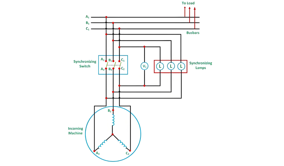
First, start the prime mover of the incoming machine and bring its speed close to the rated value. Then, adjust the field current of the incoming machine so that its output voltage matches the bus voltage. As the incoming machine approaches synchronization, the three synchronizing lamps will flicker at a rate corresponding to the difference in frequencies between the incoming machine and the bus. When the phases are correctly connected, all three lamps will simultaneously illuminate and dim. If this does not occur, it indicates an incorrect phase sequence.
To correct the phase sequence, simply interchange any two of the incoming machine's line leads. Next, fine - tune the frequency of the incoming machine until the lamps flicker very slowly, with a rate of less than one complete dark cycle per second. Once the incoming voltage has been properly adjusted, close the synchronizing switch precisely at the midpoint of the lamps' dark period.
Advantages of the Dark Lamp Method
Disadvantages of the Dark Lamp Method
Three Bright Lamp Method
In the three - bright - lamp method, the lamps are cross - connected across the phases: A1 is linked to B2, B1 to C2, and C1 to A2. When all three lamps brighten and dim simultaneously, it confirms that the phase sequence is correct. The optimal moment to close the synchronizing switch is at the peak of the lamps' bright period.
Two Bright One Dark Lamp Method
In this approach, one lamp is connected between corresponding phases, while the other two lamps are cross - connected between the remaining two phases, as depicted in the figure below.
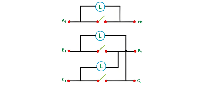
In this method, the connections are made as follows: A1 is connected to A2, B1 to C2, and C1 to B2. First, start the prime mover of the incoming machine and accelerate it to its rated speed. Then, adjust the excitation of the incoming machine. Through this adjustment, the incoming machine will induce voltages EA1, EB2, EC3, which should match the busbar voltages VA1, VB1, and VC1 respectively. The corresponding connection diagram is presented below.
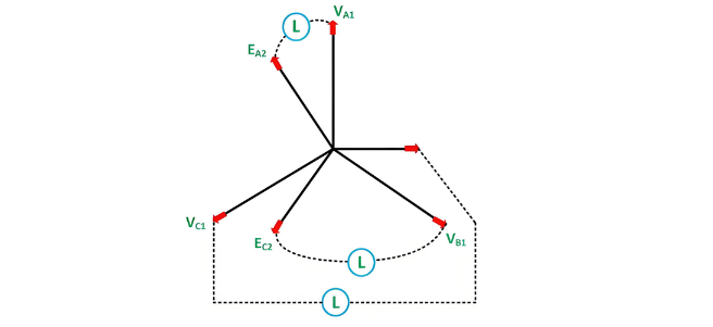
The optimal moment to close the switch occurs when the directly - connected lamp is dark and the cross - connected lamps are of equal brightness. If the phase sequence is incorrect, this specific instant will not occur; instead, all the lamps will go dark simultaneously.
To change the direction of rotation of the incoming machine, two of its line connections are interchanged. Given that the dark state of the lamp can occur over a relatively wide voltage range, a voltmeter is connected across the directly - connected lamp. The synchronizing switch is then closed precisely when the voltmeter reading reaches zero.
Once the switch is closed, the incoming machine is now connected to the busbar in a "floating" state, ready to function as a generator and assume the load. Conversely, if the prime mover is disconnected, the machine will operate as an electric motor.
In power stations, when paralleling small machines, a combination of three synchronizing lamps and a synchroscope is typically employed. For the synchronization of very large machines, however, the entire process is automated and executed by a computer system, ensuring high precision and reliability.


