Starting of an Induction Motor

Three - Phase Induction Motors: Self - Starting Mechanism and Starting Methods
A three - phase induction motor is inherently self - starting. When the power supply is connected to the stator of a three - phase induction motor, a rotating magnetic field is generated. This rotating magnetic field interacts with the rotor, causing it to start rotating and initiating the operation of the induction motor. At the moment of starting, the motor slip is equal to 1, and the starting current is significantly high.
The role of a starter in a three - phase induction motor extends beyond mere starting. It serves two primary functions:
There are two fundamental approaches to starting a three - phase induction motor. One method involves connecting the motor directly to the full supply voltage. The other approach entails applying a reduced voltage to the motor at startup. It's important to note that the torque produced by an induction motor is proportional to the square of the applied voltage. Consequently, a motor generates significantly more torque when started at full voltage compared to when it is started with reduced voltage.
For cage induction motors, which are widely used in industrial and commercial applications, there are three main starting methods:

Starting Methods for Induction Motors
Direct - on - Line Starter
The direct - on - line (DOL) starter method for induction motors is renowned for its simplicity and cost - effectiveness. With this approach, the motor is directly connected to the full supply voltage. This straightforward method is typically employed for small motors with a rating of up to 5 kW. By using a DOL starter for these smaller motors, potential fluctuations in the supply voltage can be minimized, ensuring stable operation of the electrical system.
Star - Delta Starter
The star - delta starter is one of the most common and widely adopted methods for starting three - phase induction motors. In normal operation, the motor's stator windings are configured in a delta connection. However, during the starting phase, the windings are initially connected in a star configuration. This star connection reduces the voltage applied to each winding, thereby limiting the starting current. Once the motor has gained sufficient speed, the windings are then switched to the delta connection, allowing the motor to operate at its full - rated performance.
Autotransformer Starter
Autotransformers can be used in either star - connected or delta - connected configurations. Their primary function in the context of induction motor starting is to limit the starting current. By adjusting the turns ratio of the autotransformer, the voltage supplied to the motor during startup can be reduced. This controlled reduction in voltage helps to mitigate the high inrush current that occurs when the motor is first energized, protecting both the motor and the electrical supply system.
The direct - on - line, star - delta, and autotransformer starters are specifically designed for cage rotor induction motors, which are prevalent in a wide range of industrial and commercial applications due to their robust construction and reliable operation.
Slip Ring Induction Motor Starter Method
For slip ring induction motors, the starting process involves connecting the full supply voltage across the starter. The unique design of slip ring motors, with their external rotor circuits, allows for additional control during starting. The connection diagram of a slip ring induction motor starter provides a visual representation of how the various components interact to facilitate the starting process, enabling better understanding of its operation and control mechanisms.
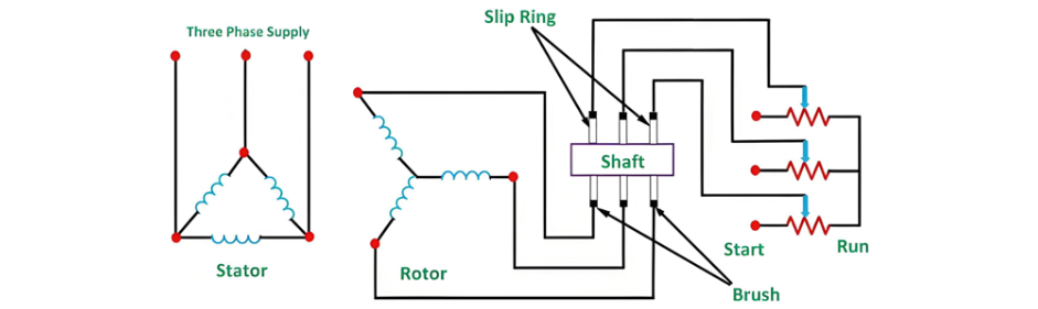
When starting a slip ring induction motor, the full starting resistance is initially connected in the rotor circuit. This effectively reduces the supply current drawn by the stator, minimizing the inrush current that could otherwise stress the electrical system and the motor itself. As the electrical supply energizes the motor, the rotor begins to rotate.
As the motor accelerates, the rotor resistances are systematically reduced in stages. This gradual cutting - out of the resistances is carefully coordinated with the increase in the motor's rotational speed. By doing so, the motor can smoothly build up its speed while maintaining optimal torque characteristics.
Once the motor reaches its rated full - load speed, all the starting resistances are completely removed from the circuit. At this point, the slip rings are short - circuited. This short - circuiting allows the motor to operate with maximum efficiency, as it eliminates the additional resistance that was only necessary during the starting phase, enabling the motor to deliver its full - rated performance.


