• Product
  • Suppliers
  • Manufacturers
  • Solutions
  • Free tools
  • Knowledges
  • Experts
  • Communities
Search


Speed Control of an Induction Motor

Edwiin
Edwiin
Field: Power switch
China

There are multiple methods for controlling the speed of an induction motor. The rotor speed of an induction motor is determined by the equation presented below. From equation (1), it becomes evident that the motor's speed can be modified by altering the frequency f, the number of poles P, or the slip s. To achieve the desired speed adjustment, one can employ any single method from the following list or combine multiple techniques. All of these induction - motor speed - control methods find practical applications in real - world scenarios.

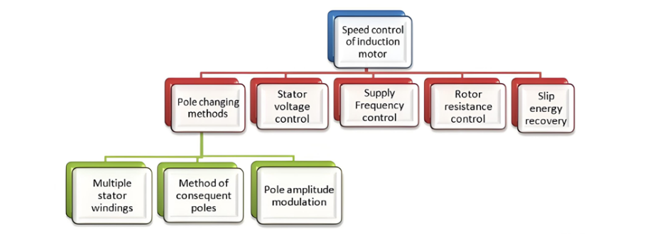
The speed - control methods for induction motors are as follows:
Pole Changing
The pole - changing method can be further categorized into three distinct types:

  • Method of Consequent Poles: This approach leverages specific magnetic configurations to change the effective number of poles in the motor.

  • Multiple Stator Windings: By utilizing different sets of windings on the stator, the number of poles can be adjusted, thereby influencing the motor's speed.

  • Pole Amplitude Modulation: A more sophisticated technique that modulates the amplitude of the magnetic poles to achieve speed variation.

Other Methods

  • Stator Voltage Control: Adjusting the voltage supplied to the stator can impact the motor's performance and speed.

  • Supply Frequency Control: Altering the frequency of the electrical supply directly affects the rotational speed of the induction motor.

  • Rotor Resistance Control: Modifying the resistance in the rotor circuit can change the motor's speed - torque characteristics and achieve speed control.

  • Slip Energy Recovery: This method focuses on recovering and utilizing the energy associated with the slip to regulate the motor's speed more efficiently.

Each of these speed - control methods is described in detail in the relevant sections, providing an in - depth understanding of their operation, advantages, and applications.

Give a tip and encourage the author!
Recommended
SST Technology: Full-Scenario Analysis in Power Generation, Transmission, Distribution, and Consumption
I. Research BackgroundPower System Transformation NeedsChanges in energy structure are placing higher demands on power systems. Traditional power systems are transitioning toward new-generation power systems, with the core differences between them outlined as follows: Dimension Traditional Power System New-Type Power System Technical Foundation Form Mechanical Electromagnetic System Dominated by Synchronous Machines and Power Electronic Equipment Generation-Side Form M
Echo
10/28/2025
Rectifier vs Power Transformer: Key Differences
Differences Between Rectifier Transformers and Power TransformersRectifier transformers and power transformers both belong to the transformer family, but they differ fundamentally in application and functional characteristics. The transformers commonly seen on utility poles are typically power transformers, while those supplying electrolytic cells or electroplating equipment in factories are usually rectifier transformers. Understanding their differences requires examining three aspects: working
Echo
10/27/2025
SST Transformer Core Loss Calculation and Winding Optimization Guide
SST High-Frequency Isolated Transformer Core Design and Calculation Material Characteristics Impact:Core material exhibits varying loss behavior under different temperatures, frequencies, and flux densities. These characteristics form the foundation of overall core loss and require precise understanding of nonlinear properties. Stray Magnetic Field Interference:High-frequency stray magnetic fields around windings can induce additional core losses. If not properly managed, these parasitic losses
Dyson
10/27/2025
Upgrade Traditional Transformers: Amorphous or Solid-State?
I. Core Innovation: A Dual Revolution in Materials and StructureTwo key innovations:Material Innovation: Amorphous AlloyWhat it is: A metallic material formed by ultra-rapid solidification, featuring a disordered, non-crystalline atomic structure.Key Advantage: Extremely low core loss (no-load loss), which is 60%–80% lower than that of traditional silicon steel transformers.Why it matters: No-load loss occurs continuously, 24/7, throughout a transformer’s lifecycle. For transformers with low loa
Echo
10/27/2025
Send inquiry
Download
Get the IEE Business Application
Use the IEE-Business app to find equipment, obtain solutions, connect with experts, and participate in industry collaboration anytime, anywhere—fully supporting the development of your power projects and business.