Abnormal Operating Condition and Causes of Induction Motors

Field: Power switch
China
Abnormal Operating Conditions and Causes of Induction Motors
Three-phase induction motors are widely used in industrial applications. Their abnormal operating conditions and causes can be summarized as follows:
Abnormal Operating Conditions and Causes of Induction Motors
The following are the abnormal operating conditions and causes of induction motors:
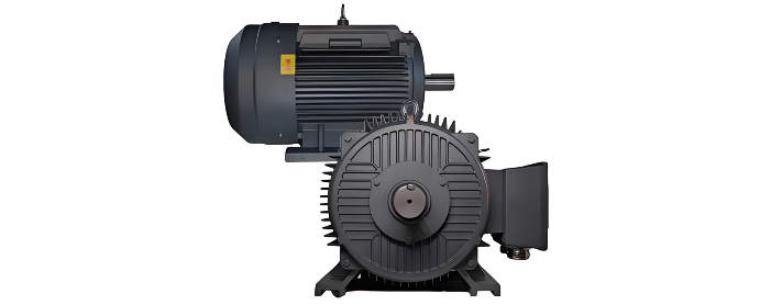
Mechanical Overload
Abnormal Supply Conditions
Internal Motor Faults
Give a tip and encourage the author!
Recommended

SST Technology: Full-Scenario Analysis in Power Generation, Transmission, Distribution, and Consumption
I. Research BackgroundPower System Transformation NeedsChanges in energy structure are placing higher demands on power systems. Traditional power systems are transitioning toward new-generation power systems, with the core differences between them outlined as follows: Dimension Traditional Power System New-Type Power System Technical Foundation Form Mechanical Electromagnetic System Dominated by Synchronous Machines and Power Electronic Equipment Generation-Side Form M
10/28/2025

SST Transformer Core Loss Calculation and Winding Optimization Guide
SST High-Frequency Isolated Transformer Core Design and Calculation Material Characteristics Impact:Core material exhibits varying loss behavior under different temperatures, frequencies, and flux densities. These characteristics form the foundation of overall core loss and require precise understanding of nonlinear properties. Stray Magnetic Field Interference:High-frequency stray magnetic fields around windings can induce additional core losses. If not properly managed, these parasitic losses
10/27/2025

Design of a Four-Port Solid-State Transformer: Efficient Integration Solution for Microgrids
The use of power electronics in industry is increasing, ranging from small-scale applications such as chargers for batteries and LED drivers, to large-scale applications like photovoltaic (PV) systems and electric vehicles. Typically, a power system consists of three parts: power plants, transmission systems, and distribution systems. Traditionally, low-frequency transformers are used for two purposes: electrical isolation and voltage matching. However, 50-/60-Hz transformers are bulky and heavy
10/27/2025

SST vs Traditional Transformer: Key Advantages
Solid-State Transformers (SST): The Future of Intelligent Power ConversionA solid-state transformer (SST), also known as a power electronic transformer (PET), is a static power conversion device that integrates power electronics, high-frequency transformation, and advanced control systems based on electromagnetic induction. It enables the conversion of electrical energy from one set of voltage, current, and frequency characteristics to another—while offering active control, bidirectional power f
10/27/2025


