• Product
  • Suppliers
  • Manufacturers
  • Solutions
  • Free tools
  • Knowledges
  • Experts
  • Communities
Search


Stator Voltage Control of an Induction Motor

Edwiin
Edwiin
Field: Power switch
China

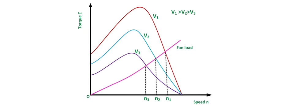
Stator voltage control represents a method employed to regulate the speed of an induction motor. The rotational speed of a three-phase induction motor can be adjusted by varying the supply voltage. As is well established, the torque generated by the motor is proportional to the square of the supply voltage, while the slip at the point of maximum torque remains independent of the supply voltage. Notably, fluctuations in the supply voltage do not affect the synchronous speed of the motor.

The torque-speed characteristics of three-phase induction motors under different supply voltages, along with the characteristics for a fan load, are illustrated below:

Stator voltage control is a technique used to regulate the speed of an induction motor. The rotational speed of a three-phase induction motor can be adjusted by varying the supply voltage. The torque generated by the motor is proportional to the square of the supply voltage, while the current is directly proportional to the voltage. Thus, the speed is controlled by adjusting the voltage until the motor develops the torque required by the load at the desired speed.

To reduce the speed while maintaining the same current, the voltage is decreased, which in turn reduces the torque output. This stator voltage control method is particularly suitable for applications where the load torque decreases with speed, such as fan loads.

This approach allows speed control only below the normal rated speed, as operating at voltages higher than the rated value is not permissible. It is ideal for drives requiring intermittent operation, as well as fan and pump systems, where the load torque varies with the square of the speed. These drives demand lower torque at lower speeds, a condition that can be met by applying a lower voltage without exceeding the motor's current rating.

For speed control of small-sized motors (primarily single-phase), variable voltage can be achieved through the following methods:

  • Connecting an external resistance in the motor's stator circuit.

  • Using an auto-transformer.

  • Employing a thyristor voltage controller.

  • Utilizing a triac controller.

The thyristor voltage controller method is now the preferred choice for voltage variation. For a single-phase supply, two thyristors are connected back-to-back, as illustrated in the figure below:

The domestic fan motors, which are single-phase are controlled by a single-phase Triac Voltage Controller as shown in the figure below:

Speed control is achieved by adjusting the firing angle of the Triac. These controllers are commonly referred to as solid-state fan regulators. Compared to conventional variable regulators, solid-state regulators offer greater compactness and efficiency, making them the preferred choice over traditional regulators.

For a three-phase induction motor, three pairs of thyristors are required, with each pair consisting of two thyristors connected back-to-back. The diagram below illustrates the stator voltage control of three-phase induction motors using a thyristor voltage controller:

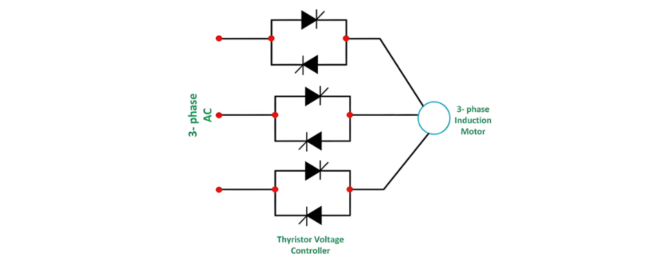
Each pair of thyristors controls the voltage of the corresponding phase. Speed regulation is achieved by adjusting the conduction period of the thyristors. For lower power ratings, the back-to-back thyristor pairs in each phase can be replaced by a Triac.

Give a tip and encourage the author!
Recommended
SST Technology: Full-Scenario Analysis in Power Generation, Transmission, Distribution, and Consumption
I. Research BackgroundPower System Transformation NeedsChanges in energy structure are placing higher demands on power systems. Traditional power systems are transitioning toward new-generation power systems, with the core differences between them outlined as follows: Dimension Traditional Power System New-Type Power System Technical Foundation Form Mechanical Electromagnetic System Dominated by Synchronous Machines and Power Electronic Equipment Generation-Side Form M
Echo
10/28/2025
Rectifier vs Power Transformer: Key Differences
Differences Between Rectifier Transformers and Power TransformersRectifier transformers and power transformers both belong to the transformer family, but they differ fundamentally in application and functional characteristics. The transformers commonly seen on utility poles are typically power transformers, while those supplying electrolytic cells or electroplating equipment in factories are usually rectifier transformers. Understanding their differences requires examining three aspects: working
Echo
10/27/2025
SST Transformer Core Loss Calculation and Winding Optimization Guide
SST High-Frequency Isolated Transformer Core Design and Calculation Material Characteristics Impact:Core material exhibits varying loss behavior under different temperatures, frequencies, and flux densities. These characteristics form the foundation of overall core loss and require precise understanding of nonlinear properties. Stray Magnetic Field Interference:High-frequency stray magnetic fields around windings can induce additional core losses. If not properly managed, these parasitic losses
Dyson
10/27/2025
Upgrade Traditional Transformers: Amorphous or Solid-State?
I. Core Innovation: A Dual Revolution in Materials and StructureTwo key innovations:Material Innovation: Amorphous AlloyWhat it is: A metallic material formed by ultra-rapid solidification, featuring a disordered, non-crystalline atomic structure.Key Advantage: Extremely low core loss (no-load loss), which is 60%–80% lower than that of traditional silicon steel transformers.Why it matters: No-load loss occurs continuously, 24/7, throughout a transformer’s lifecycle. For transformers with low loa
Echo
10/27/2025
Send inquiry
Download
Get the IEE Business Application
Use the IEE-Business app to find equipment, obtain solutions, connect with experts, and participate in industry collaboration anytime, anywhere—fully supporting the development of your power projects and business.