• Product
  • Suppliers
  • Manufacturers
  • Solutions
  • Free tools
  • Knowledges
  • Experts
  • Communities
Search


Slip Energy Recovery of an Induction Motor

Edwiin
Edwiin
Field: Power switch
China

Slip Energy Recovery, a sophisticated technique for regulating the speed of an induction motor, is alternatively referred to as the Static Scherbius Drive. In traditional rotor resistance control methods, during low-speed operation, the slip power within the rotor circuit is predominantly dissipated as I₂R losses, leading to significant energy waste and a notable reduction in system efficiency.By contrast, the slip energy recovery mechanism enables the capture of this otherwise wasted slip power from the rotor circuit and redirects it back to the AC source, allowing for its practical utilization outside the motor. This innovative approach not only mitigates energy loss but also substantially enhances the overall efficiency of the drive system.The diagram below illustrates the detailed connection configuration and operational methodology for slip energy recovery and power reclamation in an induction motor setup:

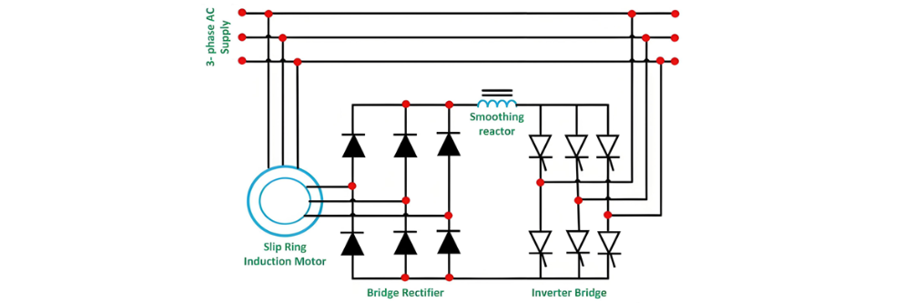
The fundamental principle of slip power recovery involves connecting an external electromotive force (EMF) source to the rotor circuit at the slip frequency. This technique enables speed control of a slip-ring induction motor below its synchronous speed. A portion of the rotor's alternating current (AC) power—known as slip power—is first converted to direct current (DC) via a diode bridge rectifier.A smoothing reactor is incorporated to stabilize the pulsating rectified current, ensuring a consistent DC output. This DC power is then fed into the inverter, which operates as a controlled rectifier in inversion mode. The inverter converts the DC power back to AC and redirects it to the main AC source, completing the energy recovery cycle.This speed control method is particularly suited for high-power applications where wide-range speed variations generate substantial slip power, making energy recovery both technically feasible and economically advantageous.

Give a tip and encourage the author!
Recommended
SST Technology: Full-Scenario Analysis in Power Generation, Transmission, Distribution, and Consumption
I. Research BackgroundPower System Transformation NeedsChanges in energy structure are placing higher demands on power systems. Traditional power systems are transitioning toward new-generation power systems, with the core differences between them outlined as follows: Dimension Traditional Power System New-Type Power System Technical Foundation Form Mechanical Electromagnetic System Dominated by Synchronous Machines and Power Electronic Equipment Generation-Side Form M
Echo
10/28/2025
Rectifier vs Power Transformer: Key Differences
Differences Between Rectifier Transformers and Power TransformersRectifier transformers and power transformers both belong to the transformer family, but they differ fundamentally in application and functional characteristics. The transformers commonly seen on utility poles are typically power transformers, while those supplying electrolytic cells or electroplating equipment in factories are usually rectifier transformers. Understanding their differences requires examining three aspects: working
Echo
10/27/2025
SST Transformer Core Loss Calculation and Winding Optimization Guide
SST High-Frequency Isolated Transformer Core Design and Calculation Material Characteristics Impact:Core material exhibits varying loss behavior under different temperatures, frequencies, and flux densities. These characteristics form the foundation of overall core loss and require precise understanding of nonlinear properties. Stray Magnetic Field Interference:High-frequency stray magnetic fields around windings can induce additional core losses. If not properly managed, these parasitic losses
Dyson
10/27/2025
Upgrade Traditional Transformers: Amorphous or Solid-State?
I. Core Innovation: A Dual Revolution in Materials and StructureTwo key innovations:Material Innovation: Amorphous AlloyWhat it is: A metallic material formed by ultra-rapid solidification, featuring a disordered, non-crystalline atomic structure.Key Advantage: Extremely low core loss (no-load loss), which is 60%–80% lower than that of traditional silicon steel transformers.Why it matters: No-load loss occurs continuously, 24/7, throughout a transformer’s lifecycle. For transformers with low loa
Echo
10/27/2025
Send inquiry
Download
Get the IEE Business Application
Use the IEE-Business app to find equipment, obtain solutions, connect with experts, and participate in industry collaboration anytime, anywhere—fully supporting the development of your power projects and business.