• Product
  • Suppliers
  • Manufacturers
  • Solutions
  • Free tools
  • Knowledges
  • Experts
  • Communities
Search


Torque Pulse Rate Characteristics of Stepper Motors and Interpretation of Pull-in Pull-out Torque Curves

Edwiin
Edwiin
Field: Power switch
China

The torque pulse rate characteristics of a stepper motor describe the variation of electromagnetic torque as a function of stepping rate in pulses per second (PPS). There are two characteristic curves, Curve 1 and Curve 2, shown in the figure below.

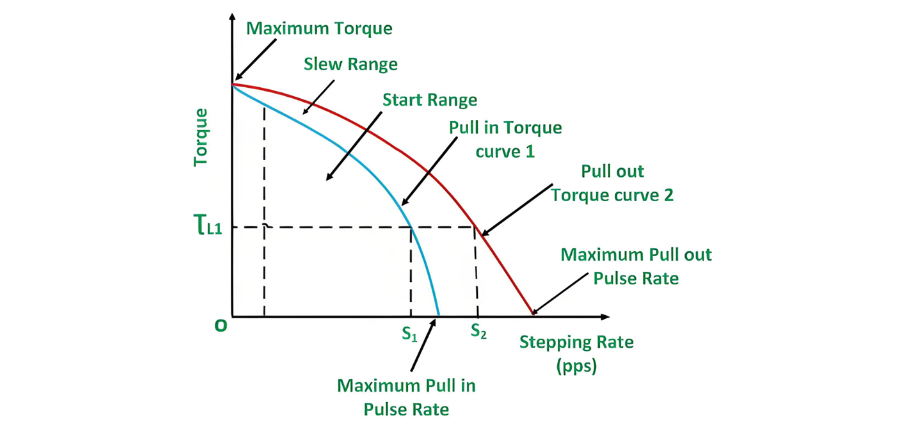
Curve 1, represented by a blue line, is known as the pull-in torque curve. It indicates the maximum stepping rate at which the motor can start, synchronize, stop, or reverse under different load torque values. Similarly, Curve 2, shown as a red line, is called the pull-out torque characteristic curve. It demonstrates the maximum stepping rate at which the motor can continue running under various load torque conditions, but at this rate, the motor is unable to start, stop, or reverse.

Let's gain a better understanding with an example based on the above curves.

For a load torque of ƮL, the motor can start, synchronize, stop, or reverse when the pulse rate is lower than S1. Once the rotor starts rotating and achieves synchronization, the stepping rate can be increased under the same load. For instance, with a load torque of ƮL1, after the motor starts and synchronizes, the stepping rate can be raised up to S2 without losing synchronization.

If the stepping rate exceeds S2, the motor will lose synchronization. Therefore, the area between Curve 1 and Curve 2 represents the range of stepping rates corresponding to different torque values within which the motor can maintain synchronization after being started and synchronized. This range is known as the slew range, and the motor is said to be operating in the slewing mode.

Give a tip and encourage the author!
Recommended
SST Technology: Full-Scenario Analysis in Power Generation, Transmission, Distribution, and Consumption
I. Research BackgroundPower System Transformation NeedsChanges in energy structure are placing higher demands on power systems. Traditional power systems are transitioning toward new-generation power systems, with the core differences between them outlined as follows: Dimension Traditional Power System New-Type Power System Technical Foundation Form Mechanical Electromagnetic System Dominated by Synchronous Machines and Power Electronic Equipment Generation-Side Form M
Echo
10/28/2025
Rectifier vs Power Transformer: Key Differences
Differences Between Rectifier Transformers and Power TransformersRectifier transformers and power transformers both belong to the transformer family, but they differ fundamentally in application and functional characteristics. The transformers commonly seen on utility poles are typically power transformers, while those supplying electrolytic cells or electroplating equipment in factories are usually rectifier transformers. Understanding their differences requires examining three aspects: working
Echo
10/27/2025
SST Transformer Core Loss Calculation and Winding Optimization Guide
SST High-Frequency Isolated Transformer Core Design and Calculation Material Characteristics Impact:Core material exhibits varying loss behavior under different temperatures, frequencies, and flux densities. These characteristics form the foundation of overall core loss and require precise understanding of nonlinear properties. Stray Magnetic Field Interference:High-frequency stray magnetic fields around windings can induce additional core losses. If not properly managed, these parasitic losses
Dyson
10/27/2025
Upgrade Traditional Transformers: Amorphous or Solid-State?
I. Core Innovation: A Dual Revolution in Materials and StructureTwo key innovations:Material Innovation: Amorphous AlloyWhat it is: A metallic material formed by ultra-rapid solidification, featuring a disordered, non-crystalline atomic structure.Key Advantage: Extremely low core loss (no-load loss), which is 60%–80% lower than that of traditional silicon steel transformers.Why it matters: No-load loss occurs continuously, 24/7, throughout a transformer’s lifecycle. For transformers with low loa
Echo
10/27/2025
Send inquiry
Download
Get the IEE Business Application
Use the IEE-Business app to find equipment, obtain solutions, connect with experts, and participate in industry collaboration anytime, anywhere—fully supporting the development of your power projects and business.