How a Single-Stack Variable Reluctance Stepper Motor Works: Stator, Rotor, and Phases

Field: Power switch
China
A single-stack variable reluctance stepper motor features a salient-pole stator with concentrated windings mounted directly on the stator poles. The number of phases is determined by the connection configuration of these windings, typically comprising three or four windings. The rotor is constructed from ferromagnetic material and contains no windings.
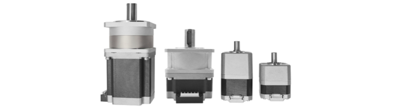
Both the stator and rotor are made of high-quality, high-permeability magnetic materials, requiring only a small exciting current to produce a strong magnetic field. When a DC source is applied to a stator phase via a semiconductor switch, a magnetic field is generated, causing the rotor axis to align with the stator field axis.
Give a tip and encourage the author!
Recommended

SST Technology: Full-Scenario Analysis in Power Generation, Transmission, Distribution, and Consumption
I. Research BackgroundPower System Transformation NeedsChanges in energy structure are placing higher demands on power systems. Traditional power systems are transitioning toward new-generation power systems, with the core differences between them outlined as follows: Dimension Traditional Power System New-Type Power System Technical Foundation Form Mechanical Electromagnetic System Dominated by Synchronous Machines and Power Electronic Equipment Generation-Side Form M
10/28/2025

Rectifier vs Power Transformer: Key Differences
Differences Between Rectifier Transformers and Power TransformersRectifier transformers and power transformers both belong to the transformer family, but they differ fundamentally in application and functional characteristics. The transformers commonly seen on utility poles are typically power transformers, while those supplying electrolytic cells or electroplating equipment in factories are usually rectifier transformers. Understanding their differences requires examining three aspects: working
10/27/2025

SST Transformer Core Loss Calculation and Winding Optimization Guide
SST High-Frequency Isolated Transformer Core Design and Calculation Material Characteristics Impact:Core material exhibits varying loss behavior under different temperatures, frequencies, and flux densities. These characteristics form the foundation of overall core loss and require precise understanding of nonlinear properties. Stray Magnetic Field Interference:High-frequency stray magnetic fields around windings can induce additional core losses. If not properly managed, these parasitic losses
10/27/2025

Upgrade Traditional Transformers: Amorphous or Solid-State?
I. Core Innovation: A Dual Revolution in Materials and StructureTwo key innovations:Material Innovation: Amorphous AlloyWhat it is: A metallic material formed by ultra-rapid solidification, featuring a disordered, non-crystalline atomic structure.Key Advantage: Extremely low core loss (no-load loss), which is 60%–80% lower than that of traditional silicon steel transformers.Why it matters: No-load loss occurs continuously, 24/7, throughout a transformer’s lifecycle. For transformers with low loa
10/27/2025


