Derivation & Analysis of Peak/RMS Characteristics of 1.75T Magnetic Flux Density in Oil-Immersed Transformer Core

Generally speaking, the designed working magnetic flux density of the iron core in an oil-immersed power transformer can be around 1.75T (the specific value depends on factors such as no-load loss and noise requirements). However, there is a seemingly basic yet easily confusing question: is this 1.75T magnetic flux density value a peak value or an effective value?
Even when asking an engineer with many years of experience in transformer design, they may not be able to give an accurate answer immediately. Even many people will blurt out that it is the "effective value".
In fact, to figure out this problem, one needs to have basic theoretical knowledge in transformer design. We might as well start from Faraday's law of electromagnetic induction and conduct a derivation analysis combined with calculus knowledge.
01 Derivation of the formula
When the external power supply voltage is a sine wave, the main magnetic flux in the iron core can basically be regarded as a sine wave. Let us assume the main magnetic flux in the iron core is φ = Φₘsinωt. According to Faraday's law of electromagnetic induction, the induced voltage is:

Since the external power supply voltage is approximately equal to the induced voltage of the primary coil, let U be the effective value of the external power supply voltage. Then:

Further simplification gives:

In formula (1):
U is the effective value of the primary side power phase voltage, in volts (V);
f is the frequency of the primary side power voltage, in hertz (Hz);
N is the electrical turns of the primary winding;
Bₘ is the peak value of the working magnetic flux density of the iron core, in tesla (T);
S is the effective cross-sectional area of the iron core, in square meters (m²).
It can be seen from formula (1) that since U is the effective value of the voltage (i.e., the right side of the expression has been divided by the square root of 2), Bₘ here refers to the peak value of the working magnetic flux density of the iron core, not the effective value.
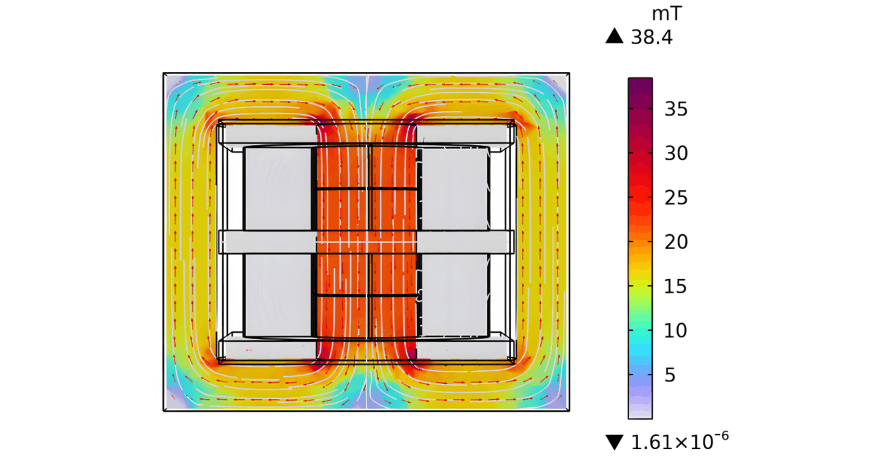
In fact, in the field of transformers, voltage, current, and current density are generally described by effective values, while magnetic flux density (in iron cores and magnetic shields) is usually described by peak values. However, it should be noted that the calculation results of magnetic flux density in some simulation software are defaulted to the effective value (RMS), such as Magnet; in other software, they are defaulted to the peak value (Peak), such as COMSOL. Special attention must be paid to these differences in software results to avoid major misunderstandings.
02 Significance of the Formula
Formula (1) is the renowned "4.44 formula" in the field of transformers and even the entire electrical engineering domain. (The result of 2π divided by the square root of 2 is exactly 4.44—could this be a coincidence in academia?)
Though simple in appearance, this formula is of great significance. It cleverly connects electricity and magnetism with a mathematical expression that even a junior high school student can understand. On the left side of the formula is the electrical quantity U, and on the right side is the magnetic quantity Bₘ.
In fact, no matter how complex the transformer design is, we can start from this formula. For instance, transformers with constant flux voltage regulation, variable flux voltage regulation, and hybrid voltage regulation. It can be said that as long as we grasp the profound connotation of this formula (a deep understanding of its connotation is crucial), the electromagnetic design of any transformer will be manageable.
This includes power transformers with side-column voltage regulation and multi-body voltage regulation, as well as special transformers such as traction transformers, phase-shifting transformers, rectifier transformers, converter transformers, furnace transformers, test transformers, and adjustable reactors. It is no exaggeration to say that this extremely simple formula has completely lifted the mysterious veil of transformers. Undoubtedly, this formula is a gateway for us to enter the scientific palace of transformers.
Sometimes, the final derived mathematical expression may obscure the physical essence. For example, when understanding this formula (1), it is particularly important to note that although from this mathematical expression, when the power frequency, the number of turns of the primary winding of the transformer, and the cross-sectional area of the iron core are fixed, the working magnetic flux density Bₘ of the iron core is uniquely determined by the external excitation voltage U, the working magnetic flux density Bₘ of the iron core is always generated by the current and obeys the superposition theorem. The conclusion that current excites the magnetic field is always correct so far.


