Analysis of Single-Phase Grounding Fault Handling and Small-Current Grounding Line Selection Device in Substations

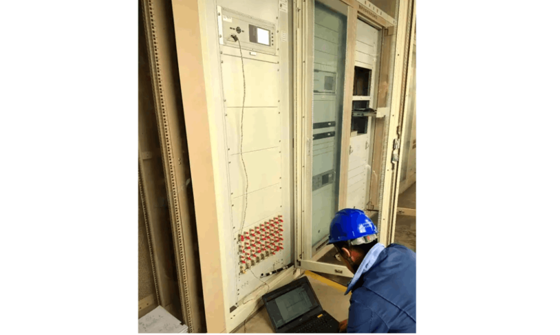
A substation without a grounding line selection device experienced a single-phase grounding fault. The fault location system (FA) pinpointed the fault section between switch A and switch B. On-site patrol and handling took 30 minutes to isolate the fault, with no need for trial tripping of non-faulty lines.The coordination between the main network and distribution network relies on a comprehensive analysis of "bus protection action, 3U0, three-phase voltage + line terminal alarm". Based on existing distribution automation equipment, there is no need to add new hardware—only software upgrades are required. Through main-distribution network coordination, line selection and section positioning can be realized.
When a single-phase grounding fault occurs, the substation bus voltage meets the grounding conditions, and the bus sends out a grounding protection signal. At this time, the distribution automation terminal of switch A on the outgoing line sends a grounding alarm signal, while switch B does not. The main station analyzes the fault based on signals from the main and distribution networks, thus locating the fault between switch A and switch B.
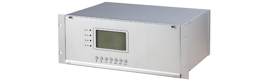
The core value of a small-current grounding line selection device lies in accurately identifying the faulty line. When a single-phase grounding fault occurs, it is the most critical tool for directly locking the source of the problem. Its primary significance is to quickly and accurately identify the specific line with the grounding fault from multiple outgoing lines.
Without it, maintenance personnel either rely on time-consuming and error-prone manual trial tripping or programmed rapid tripping—both essentially "blind scanning". Judging the fault point by cutting off lines one by one will inevitably cause non-faulty lines to be unnecessarily tripped, directly sacrificing the user's power supply experience. Frequent short-term power interruptions not only reduce voltage quality on the user side, but also pose significant risks to sensitive loads (such as precision manufacturing and data centers), which contradicts the development goals of smart distribution networks pursuing high reliability and high self-healing capabilities.
Automated coordinated line selection, though an alternative, is complex and highly dependent on multiple factors. When manual trial tripping is not relied upon and there is no dedicated line selection device, the main-distribution network coordination based on comprehensive judgment of "bus protection action, 3U0, three-phase voltage + line terminal alarm" is a feasible approach. The core of this scheme is to comprehensively use key fault information from the substation layer and distribution line layer for joint analysis.
However, this method relies on the coordination of multiple links: substation information collection and transmission (hardware foundation), line terminal coverage and reliability (data foundation), main station algorithms (core brain), and coordination mechanisms (system linkage). Its complexity, delay, and success rate are constrained by the weakest links in the entire chain, making it far less comparable to dedicated devices.
Line selection devices are by no means redundant; their accuracy determines whether they are an "anchor of stability" or a "source of accidents". A device with accurate selection is the core cornerstone for ensuring rapid isolation and minimizing power outages. However, an inaccurate device is extremely dangerous—it may lead to operation and maintenance personnel cutting off healthy lines based on wrong information, turning "precision cutting" into a disaster that "precisely causes power outages". Therefore, its necessity is absolutely tied to its performance (accuracy, reliability), and performance is the key to its survival.
Although automated coordinated line selection is a feasible solution, local conditions vary across regions, and multiple factors need to be considered. Thus, the selection should be made according to local circumstances.


