• Product
  • Suppliers
  • Manufacturers
  • Solutions
  • Free tools
  • Knowledges
  • Experts
  • Communities
Search


Armature Reaction in a DC Generator

Edwiin
Edwiin
Field: Power switch
China

Definition and Magnetic Field Effects of Armature Reaction

Definition: Armature reaction fundamentally describes the interaction between the armature magnetic field and the main field, specifically characterizing how the armature flux influences the main field flux. The armature magnetic field is generated by current-carrying armature conductors, while the main field is excited by magnetic poles. The armature flux exerts two primary effects on the main field flux:

  • Distortion of the Main Field: Armature reaction causes spatial distortion in the distribution of the main field flux;

  • Weakening of the Main Field: It simultaneously reduces the amplitude of the main field flux.

Magnetic Field Distribution in a Two-Pole DC Generator Under No-Load Condition

Consider the two-pole DC generator shown in the figure below. When the generator operates under no-load conditions (i.e., armature current is zero), only the magnetomotive force (MMF) of the main poles exists within the machine. The magnetic flux generated by the main poles' MMF is uniformly distributed along the magnetic axis, which is defined as the centerline between the north and south poles. The arrow in the figure indicates the direction of the main magnetic flux Φₘ. The magnetic neutral axis (or plane) is perpendicular to the axis of this magnetic flux.

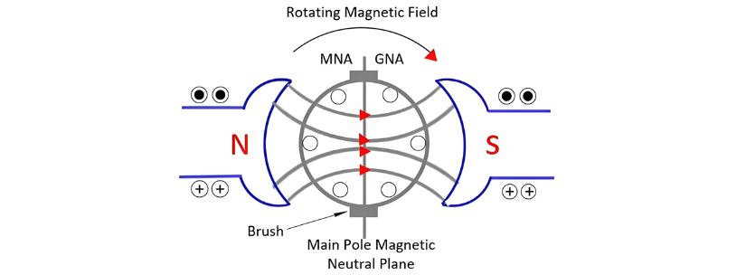
The MNA coincides with the geometrical neutral axis (GNA). The brushes of the DC machines are always placed in this axis, and hence this axis is called the axis of commutation.

Magnetic Field Analysis of Current-Carrying Armature Conductors

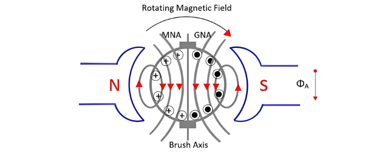
Consider a scenario where only armature conductors carry current, with no current in the main poles. The current direction is uniform for all conductors under a single pole. The direction of induced current in conductors is determined by Fleming's Right-Hand Rule, while the direction of flux generated by conductors follows the Corkscrew Rule.

Current in left-side armature conductors flows into the paper (denoted by a cross inside a circle). The magnetomotive forces (MMFs) of these conductors combine to generate a downward resultant flux through the armature. Similarly, right-side conductors carry current flowing out of the paper (denoted by a dot inside a circle), with their MMFs also combining to produce downward flux. Thus, MMFs from both sides of the conductors combine such that their resultant flux is directed downward, as indicated by the arrow for armature-conductor-induced flux Φₐ in the figure above.

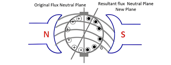
The figure below illustrates the condition where both field current and armature current act on the conductors simultaneously.

Armature Reaction Effects in Electrical Machines

Under no-load operation, the machine exhibits two magnetic fluxes: armature flux (generated by currents in armature conductors) and field pole flux (produced by main field poles). These fluxes combine to form a resultant flux Φᵣ, as illustrated in the figure above.

When field flux interacts with armature flux, distortion occurs: flux density increases at the upper tip of the N-pole and lower tip of the S-pole, while decreasing at the lower tip of the N-pole and upper tip of the S-pole. The resultant flux shifts in the direction of generator rotation, with the magnetic neutral axis (MNA)—always perpendicular to the resultant flux—moving correspondingly.

Key Effects of Armature Reaction:

  • Flux Density Asymmetry

    • Armature reaction increases flux density in one half of the pole while decreasing it in the other.

    • Total pole flux slightly decreases, reducing terminal voltage—a phenomenon called the demagnetizing effect.

  • Flux Waveform Distortion

    • The resultant flux distorts the magnetic field.

    • In generators, the MNA shifts with the resultant flux; in motors, it shifts opposite to the resultant flux.

  • Commutation Challenges

    • Armature reaction induces flux in the neutral zone, generating voltages that cause commutation issues.

  • Neutral Axis Definitions

    • The MNA is where induced EMF equals zero.

    • The geometric neutral axis (GNA) bisects the armature core symmetrically.

Give a tip and encourage the author!
Recommended
SST Technology: Full-Scenario Analysis in Power Generation, Transmission, Distribution, and Consumption
I. Research BackgroundPower System Transformation NeedsChanges in energy structure are placing higher demands on power systems. Traditional power systems are transitioning toward new-generation power systems, with the core differences between them outlined as follows: Dimension Traditional Power System New-Type Power System Technical Foundation Form Mechanical Electromagnetic System Dominated by Synchronous Machines and Power Electronic Equipment Generation-Side Form M
Echo
10/28/2025
Rectifier vs Power Transformer: Key Differences
Differences Between Rectifier Transformers and Power TransformersRectifier transformers and power transformers both belong to the transformer family, but they differ fundamentally in application and functional characteristics. The transformers commonly seen on utility poles are typically power transformers, while those supplying electrolytic cells or electroplating equipment in factories are usually rectifier transformers. Understanding their differences requires examining three aspects: working
Echo
10/27/2025
SST Transformer Core Loss Calculation and Winding Optimization Guide
SST High-Frequency Isolated Transformer Core Design and Calculation Material Characteristics Impact:Core material exhibits varying loss behavior under different temperatures, frequencies, and flux densities. These characteristics form the foundation of overall core loss and require precise understanding of nonlinear properties. Stray Magnetic Field Interference:High-frequency stray magnetic fields around windings can induce additional core losses. If not properly managed, these parasitic losses
Dyson
10/27/2025
Upgrade Traditional Transformers: Amorphous or Solid-State?
I. Core Innovation: A Dual Revolution in Materials and StructureTwo key innovations:Material Innovation: Amorphous AlloyWhat it is: A metallic material formed by ultra-rapid solidification, featuring a disordered, non-crystalline atomic structure.Key Advantage: Extremely low core loss (no-load loss), which is 60%–80% lower than that of traditional silicon steel transformers.Why it matters: No-load loss occurs continuously, 24/7, throughout a transformer’s lifecycle. For transformers with low loa
Echo
10/27/2025
Related Products
Send inquiry
Download
Get the IEE Business Application
Use the IEE-Business app to find equipment, obtain solutions, connect with experts, and participate in industry collaboration anytime, anywhere—fully supporting the development of your power projects and business.