• Product
  • Suppliers
  • Manufacturers
  • Solutions
  • Free tools
  • Knowledges
  • Experts
  • Communities
Search


Generator Protection – Types of Faults & Protection Devices

Edwiin
Edwiin
Field: Power switch
China

Common Generator Faults and Protection Systems
Classification of Generator Faults

Generator faults are primarily categorized into internal and external types:

  • Internal Faults: Arise from issues within generator components.

  • External Faults: Stem from abnormal operating conditions or external network issues.

Faults in prime movers (e.g., diesel engines, turbines) are mechanical in nature and defined during equipment design, though they must integrate with generator protections for tripping purposes.

Types of Internal Faults
1. Stator Faults

  • Winding Overheating: Caused by permanent overloads or insulation breakdown.

  • Phase-to-Phase Fault: Occurs due to insulation failure between phases.

  • Phase-to-Earth Fault: Current leakage from phase windings to the stator frame.

  • Inter-Turn Fault: Short circuit between adjacent turns in the same winding.

2. Rotor Faults

  • Earth Fault: Current leakage from rotor windings to the rotor shaft.

  • Winding Short-Circuit: Reduces excitation voltage and increases current in wound rotors.

  • Overheating: Caused by stator unbalanced currents (e.g., single-pole trip, negative phase sequence).

3. Loss of Field/Excitation

  • Reactive power flows into the generator, causing it to run as an induction generator and lose synchronism.

4. Out-of-Step Operation

  • Mechanical stresses on the shaft and voltage swings due to loss of synchronism with the grid.

5. Motor Operation

  • Generator draws power from the grid when prime mover supply fails (e.g., steam/water loss), risking overheating or cavitation in turbines.

6. Mechanical Faults

  • Bearing overheating, lubrication oil pressure loss, and excessive vibration.

Mechanism of Rotor Overheating

Unbalanced stator currents (e.g., negative phase sequence) induce eddy currents in the rotor at twice the system frequency (100/120 Hz), causing localized overheating. This weakens rotor retaining wedges and rings.

Types of External Faults
Power System Abnormalities

  • External Short-Circuits: Faults on the grid affecting generator operation.

  • Non-Synchronized Connection: Damage from improper generator paralleling.

  • Overloads/Overspeed: Caused by sudden load shedding or prime mover control failure.

  • Phase Unbalance/Negative Sequence: Induces rotor eddy currents and overheating.

  • Frequency/Voltage Deviations: Under/over frequency or voltage stressing generator components.

Generator Protection Devices
Key Protection Schemes
1. Stator Fault Protection

  • Differential Relay: Detects phase-to-phase and phase-to-earth faults by comparing input/output currents.

  • Earth Fault Protection: Uses overcurrent relays (for resistance grounding) or voltage relays (for transformer grounding) to detect stator ground faults.

2. Rotor Fault Protection

  • Earth fault relays monitor insulation breakdown between rotor windings and the shaft.

3. Unbalanced Loading Protection

  • Monitors negative phase sequence currents and loss of excitation, which cause reactive power flow issues.

4. Overheating Protection

  • Thermal relays or temperature sensors detect stator winding and bearing overheating; negative phase sequence relays address rotor heating.

5. Mechanical Protection

  • Overspeed relays, vibration sensors, and low vacuum/pressure switches safeguard against prime mover and turbine failures.

6. Backup and Supplementary Protection

  • Reverse power relays prevent motor operation, while differential relays for stator earth faults provide primary fault detection (see Figure 1 for typical connections).

  • Differential Relays: Compare currents at both ends of stator windings to detect internal faults.

Protection Principles

  • Zero-Sequence Voltage Detection: Identifies inter-turn faults by monitoring voltage imbalances via voltage transformers (VT).

  • Grounding System Adaptation: Protection schemes vary based on stator grounding methods (resistance or transformer grounding), using CTs or VTs to sense fault currents/voltages.

Rotor Winding Fault Protection Mechanisms

Wound rotor winding short-circuit faults are safeguarded by overcurrent relays, which trip the generator upon detecting abnormal current surges. Earth faults pose another risk to rotor windings, though their protection requires specialized approaches.

In large thermal generators, rotor or field windings are typically ungrounded, meaning a single ground fault does not produce a fault current. However, such a fault elevates the potential of the entire field and exciter system. Extra voltages induced by opening the field or main generator breaker—especially during fault conditions—can stress the field winding insulation, potentially causing a second ground fault. A second fault may lead to localized iron heating, rotor distortion, and dangerous mechanical unbalance.

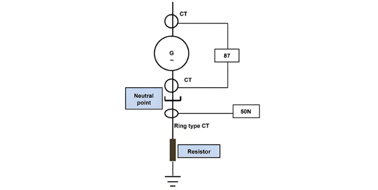
Rotor earth-fault protection often employs a relay that monitors insulation by applying an auxiliary AC voltage to the rotor. Alternatively, a voltage relay is used in series with a high-resistance network (commonly a combination of linear and non-linear resistors) across the rotor circuit. The center point of this network connects to ground via a sensitive relay coil (ANSI/IEEE/IEC code 64). Modern protection schemes increasingly favor combinations of linear and non-linear resistors for improved fault detection and insulation monitoring.

Loss of Field and Overexcitation Protection Mechanisms

Loss of field protection employs a relay to detect changes in reactive power flow. A typical scheme uses an Offset Mho (impedance) relay— a single-phase device supplied by generator current transformers (CTs) and voltage transformers (VTs)—to measure load impedance. The relay triggers when the impedance falls within its operating characteristic. A timing relay initiates generator tripping if leading reactive power persists for 1 second (standard timing).

Overexcitation Protection

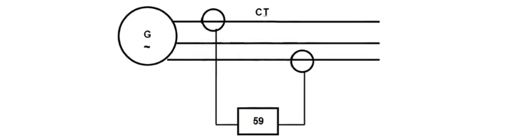
To prevent core saturation during startup and shutdown, overexcitation protection (ANSI/IEEE/IEC code 59) is implemented, based on the relationship:B = V/f
where:

  • B = magnetic flux density (tesla, T)

  • V = applied voltage (volts, V)

  • f = frequency (hertz, Hz)

Core flux must stay below the saturation point, meaning voltage can only increase proportionally with frequency (speed). Rapid excitation increases risk overexcitation, detected by Volts per Hertz relays. These relays feature linear characteristics and trip when V/f exceeds set thresholds.

Stator and Rotor Overheating Protection

  • Stator Windings & Bearings: Temperature monitoring via resistance temperature detectors (RTDs) and thermistors.

  • Stator Phase Unbalance: Time-inverse overcurrent relays set to the rotor’s maximum heat tolerance.

  • Negative Phase Sequence Protection: Shields the machine from rotor overheating caused by unbalanced stator currents, which induce damaging eddy currents in the rotor.

Reliable protection systems are critical to minimize damage and repair time, as generators are among the most expensive power system components.

This protection utilizes a relay that compares currents in two phases via current transformers (CTs), as illustrated in Figure 2. The protective settings are determined by the maximum time the rotor can endure overheating, defined by the equation K = I²t (derived from Joule's law), where I is the negative sequence current and t is the duration.

Manufacturer-specified typical time-current curves for this condition vary based on the prime mover type, as shown in the referenced diagram.

Reverse Power, Out-of-Step, and Frequency/Voltage Protection Systems
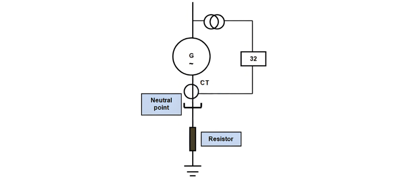
Reverse Power Protection (ANSI/IEEE/IEC Code 32)

This protection employs a power directional relay to monitor generator load, supplied by CTs and VTs (see Figure 3). The relay activates upon detecting negative power flow—indicating the generator is drawing power from the grid (motor operation)—and triggers tripping to prevent turbine damage.

Out-of-Step Protection

Designed to detect power system disturbances (not generator faults), this protection identifies pole slipping when the generator loses synchronism. It trips the generator breakers while keeping the turbine running, allowing re-synchronization after the disturbance clears.

  • Operation Principle: Three impedance relays measure load impedance. Tripping occurs if the relays activate in a specific sequence during power swings, distinguishing it from loss of excitation (which happens at zero field) and operating with the generator at full field.

Frequency and Voltage Protection
Under/Over Frequency Protection (ANSI/IEEE/IEC Code 81)

  • Overfrequency: Caused by sudden load shedding, risking overvoltage if not managed. Generator controls must adjust output to match demand.

  • Underfrequency: Results from insufficient generation for connected loads, leading to voltage drops, increased excitation, and rotor/stator overheating. Load shedding is critical to prevent system collapse.

Under/Over Voltage Relays (Codes 27/59)

Monitor and control voltage deviations to protect equipment from stress or damage.

Phase Supplementary Start Protection

Prevents starting the generator into a fault or loaded condition. Low-set overcurrent relays engage only when frequency is below 52 Hz (for 60 Hz systems) or 42 Hz (for 50 Hz systems), ensuring protection during startup transients.

External Short-Circuit Protection

Overcurrent relays (50, 50N, 51, 51N) detect and clear faults on the external network, safeguarding the generator from excessive fault currents.

These protection schemes collectively address operational anomalies—from power flow reversals to system-wide disturbances—ensuring generator integrity and grid stability.


Give a tip and encourage the author!
Recommended
SST Technology: Full-Scenario Analysis in Power Generation, Transmission, Distribution, and Consumption
I. Research BackgroundPower System Transformation NeedsChanges in energy structure are placing higher demands on power systems. Traditional power systems are transitioning toward new-generation power systems, with the core differences between them outlined as follows: Dimension Traditional Power System New-Type Power System Technical Foundation Form Mechanical Electromagnetic System Dominated by Synchronous Machines and Power Electronic Equipment Generation-Side Form M
Echo
10/28/2025
Rectifier vs Power Transformer: Key Differences
Differences Between Rectifier Transformers and Power TransformersRectifier transformers and power transformers both belong to the transformer family, but they differ fundamentally in application and functional characteristics. The transformers commonly seen on utility poles are typically power transformers, while those supplying electrolytic cells or electroplating equipment in factories are usually rectifier transformers. Understanding their differences requires examining three aspects: working
Echo
10/27/2025
SST Transformer Core Loss Calculation and Winding Optimization Guide
SST High-Frequency Isolated Transformer Core Design and Calculation Material Characteristics Impact:Core material exhibits varying loss behavior under different temperatures, frequencies, and flux densities. These characteristics form the foundation of overall core loss and require precise understanding of nonlinear properties. Stray Magnetic Field Interference:High-frequency stray magnetic fields around windings can induce additional core losses. If not properly managed, these parasitic losses
Dyson
10/27/2025
Upgrade Traditional Transformers: Amorphous or Solid-State?
I. Core Innovation: A Dual Revolution in Materials and StructureTwo key innovations:Material Innovation: Amorphous AlloyWhat it is: A metallic material formed by ultra-rapid solidification, featuring a disordered, non-crystalline atomic structure.Key Advantage: Extremely low core loss (no-load loss), which is 60%–80% lower than that of traditional silicon steel transformers.Why it matters: No-load loss occurs continuously, 24/7, throughout a transformer’s lifecycle. For transformers with low loa
Echo
10/27/2025
Related Products
Send inquiry
Download
Get the IEE Business Application
Use the IEE-Business app to find equipment, obtain solutions, connect with experts, and participate in industry collaboration anytime, anywhere—fully supporting the development of your power projects and business.