• Product
  • Suppliers
  • Manufacturers
  • Solutions
  • Free tools
  • Knowledges
  • Experts
  • Communities
Search


What are the main differences between AC and DC current in terms of their effects on conductors, capacitors, and transformers?

Encyclopedia
Encyclopedia
Field: Encyclopedia
0
China

Differences in the Impact of AC and DC on Conductors, Capacitors, and Transformers

The effects of alternating current (AC) and direct current (DC) on conductors, capacitors, and transformers differ significantly, primarily in the following aspects:

Impact on Conductors

  • Skin Effect: In AC circuits, due to electromagnetic induction, the current tends to flow near the surface of the conductor, a phenomenon known as the skin effect. This results in a reduced effective cross-sectional area of the conductor, increased resistance, and thus more energy loss. In DC circuits, the current is uniformly distributed throughout the conductor's cross-section, avoiding the skin effect.

  • Proximity Effect: When a conductor is close to another current-carrying conductor, AC causes the current to redistribute itself, leading to the proximity effect. This increases the conductor's resistance and introduces additional energy losses. DC is not affected by this phenomenon.

Impact on Capacitors

  • Charging and Discharging: AC causes capacitors to periodically charge and discharge, with voltage and current being 90 degrees out of phase. This allows capacitors to store and release energy and exhibit low impedance for high-frequency signals. In DC circuits, once the capacitor is fully charged to its maximum voltage, no further current flows through it.

  • Capacitive Reactance: Under AC, capacitors exhibit capacitive reactance, which depends on frequency and capacitance; higher frequencies result in lower reactance. In DC circuits, capacitors act as an open circuit, meaning infinite reactance.

Impact on Transformers

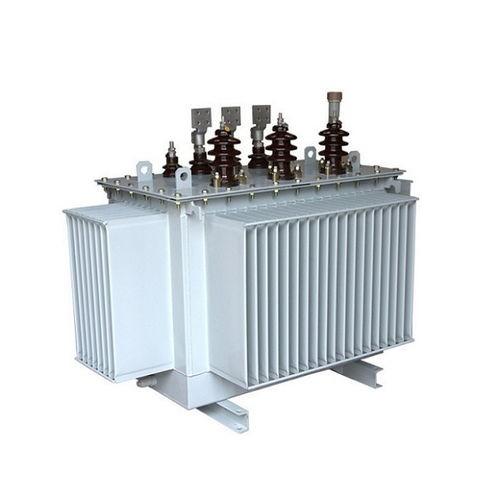
  • Operating Principle: Transformers operate based on the principle of electromagnetic induction, relying on changing magnetic fields to transfer energy. Only varying magnetic fields can induce electromotive force, so transformers are exclusively used with AC. DC cannot produce the necessary fluctuating magnetic flux within a transformer, rendering it incapable of performing voltage transformation.

  • Core Losses and Copper Losses: In AC conditions, transformers experience core losses (hysteresis and eddy current losses) and copper losses (energy lost due to winding resistance). While DC avoids core loss issues, it cannot function properly without a changing magnetic field.

In summary, the impacts of AC and DC on electrical components are determined by their respective characteristics, such as frequency and direction. These differences dictate the suitability of different types of power sources for various applications and technical requirements. By understanding these distinctions, engineers can better design and optimize electrical systems for specific needs.

Give a tip and encourage the author!
Recommended
SST Technology: Full-Scenario Analysis in Power Generation, Transmission, Distribution, and Consumption
I. Research BackgroundPower System Transformation NeedsChanges in energy structure are placing higher demands on power systems. Traditional power systems are transitioning toward new-generation power systems, with the core differences between them outlined as follows: Dimension Traditional Power System New-Type Power System Technical Foundation Form Mechanical Electromagnetic System Dominated by Synchronous Machines and Power Electronic Equipment Generation-Side Form M
Echo
10/28/2025
SST Transformer Core Loss Calculation and Winding Optimization Guide
SST High-Frequency Isolated Transformer Core Design and Calculation Material Characteristics Impact:Core material exhibits varying loss behavior under different temperatures, frequencies, and flux densities. These characteristics form the foundation of overall core loss and require precise understanding of nonlinear properties. Stray Magnetic Field Interference:High-frequency stray magnetic fields around windings can induce additional core losses. If not properly managed, these parasitic losses
Dyson
10/27/2025
Design of a Four-Port Solid-State Transformer: Efficient Integration Solution for Microgrids
The use of power electronics in industry is increasing, ranging from small-scale applications such as chargers for batteries and LED drivers, to large-scale applications like photovoltaic (PV) systems and electric vehicles. Typically, a power system consists of three parts: power plants, transmission systems, and distribution systems. Traditionally, low-frequency transformers are used for two purposes: electrical isolation and voltage matching. However, 50-/60-Hz transformers are bulky and heavy
Dyson
10/27/2025
SST vs Traditional Transformer: Key Advantages
Solid-State Transformers (SST): The Future of Intelligent Power ConversionA solid-state transformer (SST), also known as a power electronic transformer (PET), is a static power conversion device that integrates power electronics, high-frequency transformation, and advanced control systems based on electromagnetic induction. It enables the conversion of electrical energy from one set of voltage, current, and frequency characteristics to another—while offering active control, bidirectional power f
Echo
10/27/2025
Send inquiry
Download
Get the IEE Business Application
Use the IEE-Business app to find equipment, obtain solutions, connect with experts, and participate in industry collaboration anytime, anywhere—fully supporting the development of your power projects and business.