Transformer On Load Condition

Edwiin
06/03/2025

Transformer Operation Under Load Conditions
When a transformer is under load, its secondary winding connects to a load, which can be resistive, inductive, or capacitive. A current I2 flows through the secondary winding, with its magnitude determined by the terminal voltage V2 and load impedance. The phase angle between the secondary current and voltage depends on the load characteristics.
Explanation of Transformer Load Operation
The operational behavior of a transformer under load is detailed as follows:
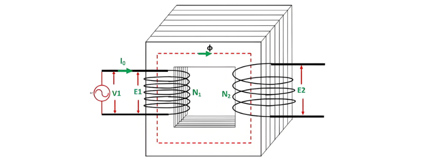
When the transformer secondary is open-circuited, it draws a no-load current from the main supply. This no-load current induces a magnetomotive force N0I0, which establishes a flux Φ in the transformer core. The circuit configuration of the transformer under no-load conditions is illustrated in the diagram below:
Transformer Load Current Interaction
When a load connects to the transformer secondary, current I2 flows through the secondary winding, inducing a magnetomotive force (MMF) N2I2. This MMF generates flux ϕ2 in the core, which opposes the original flux ϕ per Lenz's law.
Phase Difference and Power Factor in Transformer
The phase difference between V1 and I1 defines the power factor angle ϕ1 on the transformer's primary side. The secondary-side power factor depends on the load type connected to the transformer:
  • For an inductive load (as shown in the phasor diagram above), the power factor is lagging.
  • For a capacitive load, the power factor is leading.
The total primary current I1 is the vector sum of the no-load current I0 and the counter-balancing current I'1, i.e.,
Phasor Diagram of Transformer with Inductive Load
The phasor diagram of an actual transformer under inductive loading is illustrated below:
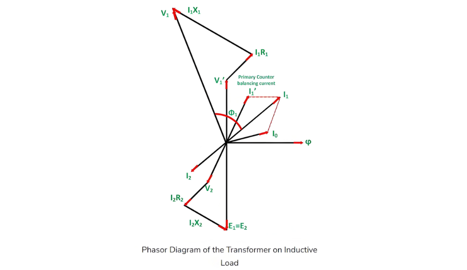
Steps to Construct the Phasor Diagram
  • Take flux Φ as the reference.
  • Induced emfs E1 and E2 lag the flux by 90°.
  • The primary applied voltage component balancing E1 is denoted as V'1 (i.e., V'1 = -E1).
  • No-load current I0lags V'1 by 90°.
  • For a lagging power factor load, current I2 lags E2 by angle ϕ2.
  • Winding resistance and leakage reactance cause voltage drops, making the secondary terminal voltage:V2 = E2 (voltage drops)
    • I2R2 is in phase with I2.
    • I2X2 is orthogonal to I2.
  • Primary current I1 is the phasor sum of I'1 and I0, where I'1 = -I2.
  • Primary applied voltage:V1 = V'1 + (primary voltage drops)
    • I1R1 is in phase with I1.
    • I1X1 is orthogonal to I1.
  • The phase difference between V1 and I1 defines the primary power factor angle ϕ1.
  • Secondary power factor:
    • Lagging for inductive loads (as in the phasor diagram).
    • Leading for capacitive loads.

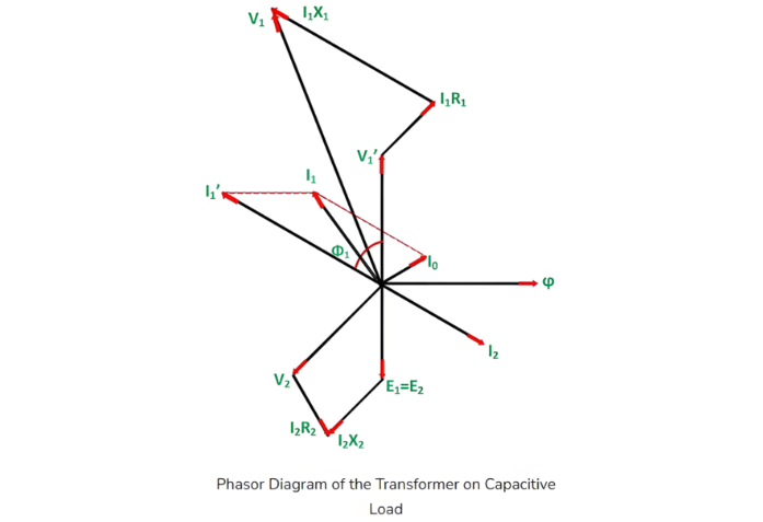
 Steps to Draw Phasor Diagram for Capacitive Load

  • Take flux Φ as the reference.
  • Induced emfs E1 and E2 lag the flux by 90°.
  • The primary applied voltage component balancing E1 is denoted as V'1 (i.e., V'1 = -E1).
  • No-load current I0 lags V'1 by 90°.
  • For a leading power factor load, current I2 leads E2 by angle ϕ2.
  • Winding resistance and leakage reactance cause voltage drops, making the secondary terminal voltage:V2 = E2 (voltage drops)
    • I2R2 is in phase with I2.
    • I2X2 is orthogonal to I2.
  • Counter-balancing current I'1 = -I2(equal in magnitude, opposite in phase to I2).
  • Primary current I1 is the phasor sum of I'1 and I0:
  • Primary applied voltage V1 is the phasor sum of V'1 and primary voltage drops:V1 = V'1 +(primary voltage drops)
    • I1R1 is in phase with I1.
    • I1X1is orthogonal to I1.
  • Power factor angles:
    • The phase difference between V1 and I1 defines the primary power factor angle ϕ1.
    • The secondary power factor (leading for capacitive loads) depends entirely on the connected load type.
Edwiin

Hello,I'm Wdwiin. A decade of hands-on experience in electrical engineering, specializing in high-voltage systems, smart grids, and renewable energy technologies. Passionate about technical exchange and knowledge sharing, committed to interpreting industry trends with professional insights to empower peers. Connection creates value—let’s explore the boundless possibilities of the electrical world together!

Can a power transformer designed for 50Hz operate normally at a frequency of 60Hz?
Can a 50Hz-Designed Power Transformer Operate on 60Hz Grid?If a power transformer is designed and built for 50Hz, can it run on a 60Hz grid? If so, how do its key performance parameters change?Key Parameter ChangesShort-Circuit Impedance:For a given transformer (same voltage and capacity), short-circuit impedance is proportional to frequency. Thus, a 50Hz-designed unit operating at 60Hz sees a 20% increase—higher frequency intensifies alternating leakage field opposition to current.No-Load
Vziman
07/29/2025
What are the basic processes and key points in transformer simulation design?
1 IntroductionWhether using any finite element analysis software (such as COMSOL, Infolytica, or Ansys) for transformer simulation analysis—whether focusing on electric field, magnetic field, flow field, mechanical field, or acoustic field—the basic process is roughly the same. A true understanding of the key points in each process is the foundation for the success of the simulation analysis and the reliability of the final results.2 Basic Simulation ProcessA scientific and complete
Ron
07/29/2025
Sharing of Transformer Concepts and Terminology
Sharing of Transformer Concepts and TerminologyThe zero-mode impedance of a load is infinite, and its line-mode impedance is also extremely large, approximately 100 times that of the line-mode impedance of the line.The capacitance to ground of a cable is 25-50 times that of an overhead line.The free oscillation frequency of transient capacitive current: 300-1500Hz for overhead lines and 1500-3000Hz for cables.Performance requirements for an external grounding transformer: Under normal power supp
Edwiin
07/28/2025
Example of Process Improvement for Enhancing Consistency of Small - Batch High - Temperature Special Transformers
Given the lack of manufacturers for such transformers on the market, we design them in - house. We provide technical specs to partners, specifying materials like high - temp enameled wires.Electrical signals from downhole logging tools, transmitted via these transformers, impact formation - to - surface signal reliability. Thus, improving transformer consistency boosts signal uniformity, enhancing logging tool accuracy and our market competitiveness.Our common signal transformers are EI - type,
Vziman
07/28/2025
Inquiry
Download
IEE-Business is dedicated to serving the personnel in the global power industry.
Join IEE-Business, not only can you discover power equipment and power knowledge, but also canhnd like - minded friends!