Transformer: What is it?


What is a Transformer?
A transformer is defined as a passive electrical device that transfers electrical energy from one circuit to another through the process of electromagnetic induction. It is most commonly used to increase (‘step up’) or decrease (‘step down’) voltage levels between circuits.
Working Principle of Transformer
The working principle of a transformer is very simple. Mutual induction between two or more windings (also known as coils) allows for electrical energy to be transferred between circuits. This principle is explained in further detail below.
Transformer Theory
Say you have one winding (also known as a coil) which is supplied by an alternating electrical source. The alternating current through the winding produces a continually changing and alternating flux that surrounds the winding.
If another winding is brought close to this winding, some portion of this alternating flux will link with the second winding. As this flux is continually changing in its amplitude and direction, there must be a changing flux linkage in the second winding or coil.
According to Faraday’s law of electromagnetic induction, there will be an EMF induced in the second winding. If the circuit of this secondary winding is closed, then a current will flow through it. This is the basic working principle of a transformer.
Let us use electrical symbols to help visualize this. The winding which receives electrical power from the source is known as the ‘primary winding’. In the diagram below this is the ‘First Coil’.

The winding which gives the desired output voltage due to mutual induction is commonly known as the ‘secondary winding’. This is the ‘Second Coil’ in the diagram above.
A transformer that increases voltage between the primary to secondary windings is defined as a step-up transformer. Conversely, a transformer that decreases voltage between the primary to secondary windings is defined as a step-down transformer.
Whether the transformer increases or decreases the voltage level depends on the relative number of turns between the primary and secondary side of the transformer.
If there are more turns on the primary coil than the secondary coil than the voltage will decrease (step down).
If there are less turns on the primary coil than the secondary coil than the voltage will increase (step up).
While the diagram of the transformer above is theoretically possible in an ideal transformer – it is not very practical. This is because in the open air only a very tiny portion of the flux produced from the first coil will link with the second coil. So the current that flows through the closed circuit connected to the secondary winding will be extremely small (and difficult to measure).
The rate of change of flux linkage depends upon the amount of linked flux with the second winding. So ideally almost all of the flux of primary winding should link to the secondary winding. This is effectively and efficiently done by using a core type transformer. This provides a low reluctance path common to both of the windings.

The purpose of the transformer core is to provide a low reluctance path, through which the maximum amount of flux produced by the primary winding is passed through and linked with the secondary winding.
The current that initially passes through the transformer when it is switched on is known as the transformer inrush current.
If you would prefer an animated explanation, below is a video explaining exactly how a transformer works:
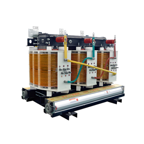
Transformer Parts And Construction
The three main parts of a transformer:
Primary Winding of Transformer
Magnetic Core of Transformer
Secondary Winding of Transformer
Primary Winding of Transformer
Which produces magnetic flux when it is connected to an electrical source.
Magnetic Core of Transformer
The magnetic flux produced by the primary winding, that will pass through this low reluctance path linked with secondary winding and create a closed magnetic circuit.
Secondary Winding of Transformer
The flux, produced by primary winding, passes through the core, will link with the secondary winding. This winding also wounds on the same core and gives the desired output of the transformer.

Statement: Respect the original, good articles worth sharing, if there is infringement please contact delete.