• Product
  • Suppliers
  • Manufacturers
  • Solutions
  • Free tools
  • Knowledges
  • Experts
  • Communities
Search


Theory of Transformer on Load and No Load Operation

Electrical4u
Electrical4u
Field: Basic Electrical
0
China

image.png

We have discussed about the theory of ideal transformer for better understanding of actual elementary theory of transformer. Now we will go through the practical aspects one by one of an electrical power transformer and try to draw vector diagram of transformer in every step. As we said that, in an ideal transformer; there are no core losses in transformer i.e. loss free core of transformer. But in practical transformer, there are hysteresis and eddy current losses in transformer core.

Theory of Transformer on No-Load

Having No Winding Resistance and No Leakage Reactance

Let us consider one electrical transformer with only core losses, which means, it has only core losses but no copper loss and no leakage reactance of transformer. When an alternating source is applied in the primary, the source will supply the current for magnetizing the core of transformer.

But this current is not the actual magnetizing current; it is a little bit greater than actual magnetizing current. Total current supplied from the source has two components, one is the magnetizing current which is merely utilized for magnetizing the core, and another component of the source current is consumed for compensating the core losses in transformers.

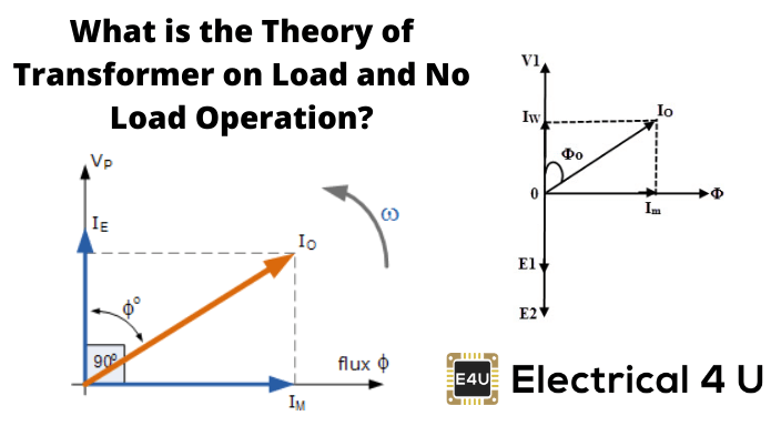
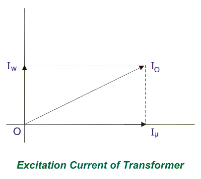
Because of this core loss component, the source current in a transformer on no-load condition supplied from the source as source current is not exactly at 90° lags of the supply voltage, but it lags behind an angle θ is less than 90o. If the total current supplied from source is Io, it will have one component in phase with supply voltage V1 and this component of the current Iw is the core loss component.

This component is taken in phase with the source voltage because it is associated with active or working losses in transformers. Another component of the source current is denoted as Iμ.

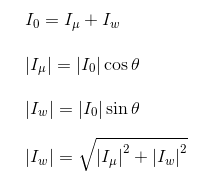
This component produces the alternating magnetic flux in the core, so it is watt-less; means it is a reactive part of the transformer source current. Hence Iμ will be in quadrature with V1 and in phase with alternating flux Φ. Hence, the total primary current in a transformer on the no-load condition can be represented as:

image.png

Now you have seen how simple it is to explain the theory of transformer in no-load.

image.png

Theory of Transformer on Load

Having No Winding Resistance and Leakage Reactance

image.png

Now we will examine the behavior of the above-said transformer on load, which means the load is connected to the secondary terminals. Consider, a transformer having core loss but no copper loss and leakage reactance. Whenever a load is connected to the secondary winding, the load current will start to flow through the load as well as the secondary winding.

This load current solely depends upon the characteristics of the load and also upon the secondary voltage of the transformer. This current is called secondary current or load current, here it is denoted as I2. As I2 is flowing through the secondary, a self MMF in secondary winding will be produced. Here it is N2I2, where, N2 is the number of turns of the secondary winding of the transformer.

image.png

This MMF or magnetomotive force in the secondary winding produces flux φ2. This φ2 will oppose the main magnetizing flux and momentarily weakens the main flux and tries to reduce primary self-induced emf E1. If E1 falls below the primary source voltage V1, there will be an extra current flowing from source to primary winding.

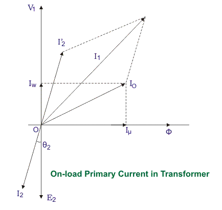
This extra primary current I2′ produces extra flux φ′ in the core which will neutralize the secondary counter flux φ2. Hence the main magnetizing flux of core, Φ remains unchanged irrespective of load. So total current, this transformer draws from the source can be divided into two components.

The first one is utilized for magnetizing the core and compensating the core loss, i.e., Io. It is the no-load component of the primary current. The second one is utilized for compensating the counter flux of the secondary winding. It is known as the load component of the primary current. Hence total no-load primary current I1 of an electrical power transformer having no winding resistance and leakage reactance can be represented as follows

Where θ2 is the angle between the Secondary Voltage and Secondary Current of the transformer.
Now we will proceed one further step toward a more practical aspect of a transformer.

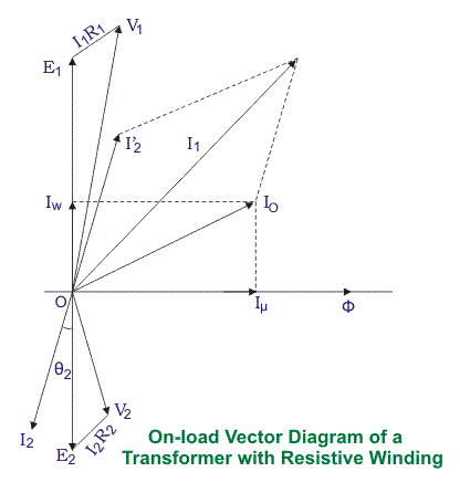
Theory of Transformer On Load, with Resistive Winding, but No Leakage Reactance

Now, consider the winding resistance of the transformer but no leakage reactance. So far we have discussed the transformer which has ideal windings, means winding with no resistance and leakage reactance, but now we will consider one transformer which has internal resistance in the winding but no leakage reactance. As the windings are resistive, there would be a voltage drop in the windings.

image.png

We have proved earlier that, total primary current from the source on load is I1. The voltage drop in the primary winding with resistance, R1 is R1I1. Obviously, induced emf across primary winding E1, is not exactly equal to source voltage V1. E1 is less than V1 by voltage drop I1R1.

image.png


Again in the case of secondary, the voltage induced across the secondary winding, E2 does not totally appear across the load since it also drops by an amount I2R2, where R2 is the secondary winding resistance and I2 is secondary current or load current.

Similarly, the voltage equation of the secondary side of the transformer will be:

image.png

Theory of Transformer On Load, with Resistance as well as Leakage Reactance

Now we will consider the condition when there is leakage reactance of the transformer as well as winding resistance of the transformer.

image.png

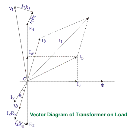
Let leakage reactances of primary and secondary windings of the transformer are X1 and X2 respectively. Hence total impedance of primary and secondary winding of transformer with resistance R1 and R2 respectively can be represented as,

image.png


We have already established the voltage equation of a transformer on load, with only resistances in the windings, where voltage drops in the windings occur only due to resistive voltage drop.

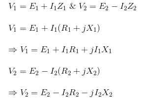
But when we consider leakage reactance of transformer windings, the voltage drop occurs in the winding not only due to resistance but also due to the impedance of transformer windings. Hence, the actual voltage equation of a transformer can easily be determined by replacing resistances R1 & R2 in the previously established voltage equations with Z1 and Z2.

Therefore, the voltage equations are,

image.png

Resistance drops are in the direction of the current vector. But a reactive drop will be perpendicular to the current vector as shown in the above vector diagram of the transformer.

Statement: Respect the original, good articles worth sharing, if there is infringement please contact delete.

Give a tip and encourage the author!
Recommended
How to Identify Internal Faults in a Transformer?
Measure DC resistance: Use a bridge to measure the DC resistance of each high- and low-voltage winding. Check whether the resistance values among phases are balanced and consistent with the manufacturer’s original data. If phase resistance cannot be measured directly, line resistance may be measured instead. The DC resistance values can indicate whether the windings are intact, whether there are short circuits or open circuits, and whether the contact resistance of the tap changer is normal. If
Felix Spark
11/04/2025
What are the requirements for inspecting and maintaining a transformer's no-load tap changer?
The tap changer operating handle shall be equipped with a protective cover. The flange at the handle shall be well sealed with no oil leakage. Locking screws shall securely fasten both the handle and the drive mechanism, and the handle rotation shall be smooth without binding. The position indicator on the handle shall be clear, accurate, and consistent with the tap voltage regulation range of the winding. Limit stops shall be provided at both extreme positions. The insulating cylinder of the t
Leon
11/04/2025
How to Overhaul a Transformer Conservator (Oil Pillow)?
Overhaul Items for Transformer Conservator:1. Ordinary-Type Conservator Remove the end covers on both sides of the conservator, clean rust and oil deposits from inner and outer surfaces, then apply insulating varnish to the inner wall and paint to the outer wall; Clean components such as the dirt collector, oil level gauge, and oil plug; Check that the connecting pipe between the explosion-proof device and the conservator is unobstructed; Replace all sealing gaskets to ensure good sealing with n
Felix Spark
11/04/2025
Why is it difficult to increase the voltage level?
The solid-state transformer (SST), also known as a power electronic transformer (PET), uses voltage level as a key indicator of its technological maturity and application scenarios. Currently, SSTs have reached voltage levels of 10 kV and 35 kV on the medium-voltage distribution side, while on the high-voltage transmission side, they remain in the stage of laboratory research and prototype validation. The table below clearly illustrates the current status of voltage levels across different appli
Echo
11/03/2025
Related Products
Send inquiry
Download
Get the IEE Business Application
Use the IEE-Business app to find equipment, obtain solutions, connect with experts, and participate in industry collaboration anytime, anywhere—fully supporting the development of your power projects and business.