• Product
  • Suppliers
  • Manufacturers
  • Solutions
  • Free tools
  • Knowledges
  • Experts
  • Communities
Search


Efficiency of Transformer

Electrical4u
Electrical4u
Field: Basic Electrical
0
China

16d6c2289f8bafeaffe95ee1086b6bc.png

Introduction of Efficiency of Transformer

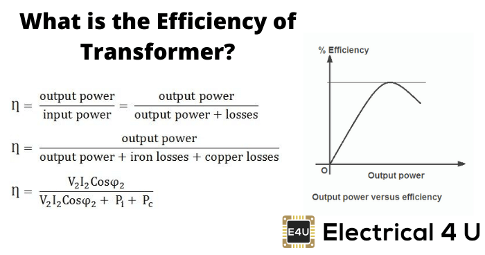
Transformers form the most important link between supply systems and load. Transformer’s efficiency directly affects its performance and aging. The transformer’s efficiency, in general, is in the range of 95 – 99 %. For large power transformers with very low losses, the efficiency can be as high as 99.7%. The input and output measurements of a transformer are not done under loaded conditions as the wattmeter readings inevitably suffer errors of 1 – 2%. So for the purpose of efficiency calculations, OC and SC tests are used to calculate rated core and winding losses in the transformer. The core losses depend on the transformer rated voltage, and the copper losses depend on the currents through the transformer primary and secondary windings. Hence transformer efficiency is of prime importance to operate it under constant voltage and frequency conditions. The rise in the temperature of the transformer due to heat generated affects the life of transformer oil properties and decides the type of cooling method adopted. The temperature rise limits the rating of the equipment. The efficiency of transformer is simply given as:

  • The output power is the product of the fraction of the rated loading (volt-ampere), and power factor of the load

  • The losses are the sum of copper losses in the windings + the iron loss + dielectric loss + stray load loss.

  • The iron losses include the hysteresis and eddy current losses in the transformer. These losses depend on the flux density inside the core. Mathematically,
    Hysteresis Loss :

    Eddy Current Loss :

    Where kh and ke are constants, Bmax is the peak magnetic field density, f is the source frequency, and t is the thickness of the core. The power ‘n’ in the hysteresis loss is known as Steinmetz constant whose value can be nearly 2.

  • The dielectric losses take place inside the transformer oil. For low voltage transformers, it can be neglected.

  • The leakage flux links to the metal frame, tank,etc. to produce eddy currents and are present all around the transformer hence called stray loss, and it depends on the load current and so named as ‘stray load loss.’ It can be represented by resistance in series to the leakage reactance.

Efficiency Calculation of the Transformer

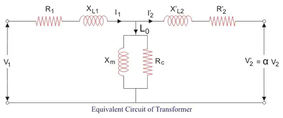
The equivalent circuit of transformer referred to primary side is shown below. Here Rc accounts for core losses. Using Short circuit(SC) test, we can find the equivalent resistance accounting for copper losses as

{CA38F734-D59B-42c6-8B13-82D0C0BF1DF5}.png

Let us define x% be the percentage of full or rated load ‘S’ (VA) and let Pcufl(watts) be the full load copper loss and cosθ be the power factor of the load. Also, we defined Pi (watts) as core loss. As copper and iron losses are major losses in the transformer hence only these two types of losses are taken into account while calculating efficiency. Then the efficiency of transformer can be written as :

Where, x2Pcufl = copper loss(Pcu) at any loading x% of full load.
The maximum efficiency (ηmax) occurs when the variable losses equal to the constant losses. Since the copper loss is load dependent, hence it is a variable loss quantity. And the core loss is taken to be the constant quantity. So the condition for maximum efficiency is :

{2FE6E547-10CA-4cf9-9224-E75E5FBB7AD1}.png

Now we can write maximum efficiency as :

This shows that we can obtain maximum efficiency at full load by proper selection of constant and variable losses. However, it is difficult to obtain maximum efficiency as copper losses are much higher than the fixed core losses.
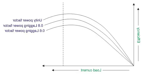
The variation of efficiency with loading can be represented by figure below :

{204A16D3-2565-42fb-ABA4-77810A760730}.png

We can see from the figure that the maximum efficiency occurs at unity power factor. And the maximum efficiency occurs at same loading irrespective of power factor of the load.


All Day Efficiency of Transformer

It is an energy-based efficiency calculated for distribution transformers. Unlike power transformer which is switched in or out depending on the load handled by it, a distribution transformer loading continuously fluctuates for 24 hours a day. As core losses are independent of load, the all-day efficiency depends on the copper losses.We define it as the ratio of output energy delivered to input energy for a 24 hour cycle. High energy efficiencies are achieved by restricting core flux densities to lower values (as the core losses are dependent on flux density) by using relatively larger cross-section or larger iron/copper weight ratio.

Statement: Respect the original, good articles worth sharing, if there is infringement please contact delete.

Give a tip and encourage the author!
Recommended
How to Identify Internal Faults in a Transformer?
Measure DC resistance: Use a bridge to measure the DC resistance of each high- and low-voltage winding. Check whether the resistance values among phases are balanced and consistent with the manufacturer’s original data. If phase resistance cannot be measured directly, line resistance may be measured instead. The DC resistance values can indicate whether the windings are intact, whether there are short circuits or open circuits, and whether the contact resistance of the tap changer is normal. If
Felix Spark
11/04/2025
What are the requirements for inspecting and maintaining a transformer's no-load tap changer?
The tap changer operating handle shall be equipped with a protective cover. The flange at the handle shall be well sealed with no oil leakage. Locking screws shall securely fasten both the handle and the drive mechanism, and the handle rotation shall be smooth without binding. The position indicator on the handle shall be clear, accurate, and consistent with the tap voltage regulation range of the winding. Limit stops shall be provided at both extreme positions. The insulating cylinder of the t
Leon
11/04/2025
How to Overhaul a Transformer Conservator (Oil Pillow)?
Overhaul Items for Transformer Conservator:1. Ordinary-Type Conservator Remove the end covers on both sides of the conservator, clean rust and oil deposits from inner and outer surfaces, then apply insulating varnish to the inner wall and paint to the outer wall; Clean components such as the dirt collector, oil level gauge, and oil plug; Check that the connecting pipe between the explosion-proof device and the conservator is unobstructed; Replace all sealing gaskets to ensure good sealing with n
Felix Spark
11/04/2025
Why is it difficult to increase the voltage level?
The solid-state transformer (SST), also known as a power electronic transformer (PET), uses voltage level as a key indicator of its technological maturity and application scenarios. Currently, SSTs have reached voltage levels of 10 kV and 35 kV on the medium-voltage distribution side, while on the high-voltage transmission side, they remain in the stage of laboratory research and prototype validation. The table below clearly illustrates the current status of voltage levels across different appli
Echo
11/03/2025
Related Products
Send inquiry
Download
Get the IEE Business Application
Use the IEE-Business app to find equipment, obtain solutions, connect with experts, and participate in industry collaboration anytime, anywhere—fully supporting the development of your power projects and business.