• Product
  • Suppliers
  • Manufacturers
  • Solutions
  • Free tools
  • Knowledges
  • Experts
  • Communities
Search


On-Line Testing for Surge Arresters Below 110kV: Safe and Efficient

Oliver Watts
Oliver Watts
Field: Inspection and testing
China

An On-Line Testing Method for Surge Arresters at 110kV and Below

In power systems, surge arresters are critical components that protect equipment from lightning overvoltage. For installations at 110kV and below—such as 35kV or 10kV substations—an on-line testing method effectively avoids the economic losses associated with power outages. The core of this method lies in using online monitoring technology to evaluate arrester performance without interrupting system operation.

The test principle is based on leakage current measurement, analyzing the resistive current component to assess aging or defects within the arrester. International standard IEC 60099-4 specifies testing requirements for surge arresters, clearly stating that regular leakage current monitoring is essential for ensuring reliability. China’s national standard GB 11032 also emphasizes the feasibility of non-intrusive testing in systems rated at 110kV and below.

Test equipment includes high-precision current transformers (CTs), a data acquisition unit, and dedicated analysis software. The CT must have wideband frequency response, covering 50 Hz to 1 MHz, to accommodate various overvoltage scenarios. The data acquisition unit should feature isolation design to prevent interference from high-voltage circuits, ensuring signal accuracy. The software incorporates algorithm models—such as Fourier transform analysis—to calculate resistive current values in real time. Equipment calibration follows metrological standards, performed at least annually, with errors verified against a standard source to remain within ±1%. Operators must hold high-voltage electrical certification and be familiar with equipment manuals to avoid operational errors.

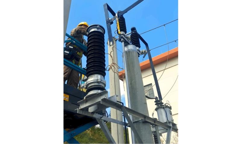
test.jpg

Implementation begins with site preparation. Select the arrester installation point, ensuring a dry environment free from strong electromagnetic interference. Before connecting equipment, verify grounding system integrity, with ground resistance below 4 ohms. Clamp the current transformer onto the arrester’s grounding lead, applying even pressure to prevent loosening. Connect the data acquisition unit to the CT output, launch the software, and set parameters such as a 1 kHz sampling rate and 5-minute measurement duration. Once recording starts, the system automatically captures the leakage current waveform. During the test, operators monitor real-time curves to identify abnormal fluctuations. After data collection, export raw files; the software automatically generates a report including peak resistive current, fundamental component, and harmonic analysis. Each step must be documented in the test log, including timestamp, ambient temperature, and humidity.

Safety measures are paramount. Conduct a risk assessment before work begins, identifying hazards such as electric shock and arc flash. Wear full protective gear, including insulating gloves, goggles, and flame-resistant clothing. Establish a safety perimeter with warning tape and “High Voltage Test” signs; unauthorized personnel must stay clear. Maintain safe distances during testing—minimum 1.5 meters for 110kV systems. Emergency preparedness includes fire extinguishers and first aid kits; if anomalies occur, immediately cut power and report. According to Article 40 of China’s Occupational Safety Law, enterprises must provide employees with no less than eight hours of annual safety training. Quality control requires test errors within ±2%, and repeated measurements must not deviate by more than 1%.

Results are analyzed using the software-generated report. A resistive current exceeding the baseline by 10% indicates aging and necessitates replacement; abnormal harmonic content suggests internal moisture or contamination. Report interpretation combines historical data to assess trends. For example, in a 35kV substation case, initial resistive current was 50μA, rising to 60μA after one year—prompt replacement prevented failure. Non-conforming results trigger maintenance workflows: complete a defect record form and notify operations teams for resolution within 48 hours. Data must be archived for at least five years for audit purposes.

This on-line method significantly improves efficiency, saving up to 90% time compared to traditional disassembly-based testing and reducing outage-related losses. Enterprises should establish annual plans, conducting tests quarterly to ensure system reliability. Continuous improvement includes adopting wireless transmission for remote monitoring. Successful implementation requires staff training to enhance technical proficiency. In summary, this method provides an efficient and safe solution for evaluating surge arresters in power systems at 110kV and below.

Give a tip and encourage the author!
Topics:
Recommended
How to Identify Internal Faults in a Transformer?
Measure DC resistance: Use a bridge to measure the DC resistance of each high- and low-voltage winding. Check whether the resistance values among phases are balanced and consistent with the manufacturer’s original data. If phase resistance cannot be measured directly, line resistance may be measured instead. The DC resistance values can indicate whether the windings are intact, whether there are short circuits or open circuits, and whether the contact resistance of the tap changer is normal. If
Felix Spark
11/04/2025
Front-Panel Visible Wiring Standards for Electrical Control Panels
Front-panel visible wiring: During manual wiring (not using templates or molds), wiring must be straight, neat, closely attached to the mounting surface, rationally routed, and with secure connections that facilitate maintenance. Wiring channels should be minimized as much as possible. Within the same channel, bottom-layer conductors shall be grouped by main and control circuits, arranged in a single-layer parallel dense layout or bundled, and kept closely attached to the mounting surface. Condu
James
11/04/2025
What are the requirements for inspecting and maintaining a transformer's no-load tap changer?
The tap changer operating handle shall be equipped with a protective cover. The flange at the handle shall be well sealed with no oil leakage. Locking screws shall securely fasten both the handle and the drive mechanism, and the handle rotation shall be smooth without binding. The position indicator on the handle shall be clear, accurate, and consistent with the tap voltage regulation range of the winding. Limit stops shall be provided at both extreme positions. The insulating cylinder of the t
Leon
11/04/2025
What Are the Common Inverter Fault Symptoms and Inspection Methods? A Complete Guide
Common inverter faults mainly include overcurrent, short circuit, ground fault, overvoltage, undervoltage, phase loss, overheating, overload, CPU malfunction, and communication errors. Modern inverters are equipped with comprehensive self-diagnostic, protection, and alarm functions. When any of these faults occurs, the inverter will immediately trigger an alarm or shut down automatically for protection, displaying a fault code or fault type. In most cases, the fault cause can be quickly identifi
Felix Spark
11/04/2025
Send inquiry
Download
Get the IEE Business Application
Use the IEE-Business app to find equipment, obtain solutions, connect with experts, and participate in industry collaboration anytime, anywhere—fully supporting the development of your power projects and business.