Vector Impedance Meter


Impedance, which is having both magnitude and phase, is truly an opponent to the flow of current in AC circuits with the presence of an applied voltage.
The Vector Impedance Meter is employed for measuring both the amplitude and phase angle of impedance (Z).
Normally, in other measuring techniques of impedance, the individual values of resistance and reactance are obtained in rectangular form. That is
But here, the impedance can be obtained in polar form. That is |Z| and phase angle (θ) of impedance can be acquired by this meter. The circuit is shown below.
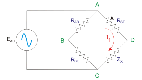
Two resistors with equal resistance values are incorporated here. The voltage drop across RAB is EAB and that of RBC is EBC. Both the values are the same and it is equal to half the value of input voltage (EAC).
A variable standard resistance (RST) is connected in series with the impedance (ZX) which the value has to be obtained.
The equal deflection method is used for the determination of the magnitude of the unknown impedance.
This is by achieving the equal voltage drops across the variable resistor and the impedance (EAD = ECD) and evaluating the calibrated standard resistor (here it is RST) which is also necessary for achieving this condition.
The phase angle of the impedance (θ) can be acquired from taking the voltage reading across BD. Here it is EBD.
The meter deflection will vary in accordance with the Q factor (quality factor) of the connected unknown impedance.
The Vacuum Tube Voltmeter (VTVM) normally reads AC voltage which varies from 0V to maximum value. When the voltage reading is zero, the value of Q will be zero and the phase angle will be 0o.
When the voltage reading becomes the maximum value, the value of Q will be infinite and the phase angle will be 90o.
The angle between EAB and EAD will be equal to θ/2 (half of the phase angle of the unknown impedance). This is because EAD = EDC.

We know that the voltage across A and B (EAB) will be equal to half of the voltage across A and C (EAC which is the input voltage). The reading of voltmeter, EDB can be thus obtained in terms of θ/2. Hence, θ (phase angle) can be determined. The vector diagram is shown below.
For obtaining the first approximation of the magnitude and phase angle of the impedance, this method is preferred. For achieving more accuracy in measurement the commercial vector impedance meter is preferred.
Commercial Vector Impedance Meter
Impedance can be straight away measured by using a commercial vector impedance meter in polar form. Only a single balancing control is used in this for getting both the phase angle and magnitude of the impedance.
This method can be used to determine any combination of resistance (R), Capacitance (C), and Inductance (L). In addition to this, it can measure complex impedances rather than pure elements (C, L, or R).
The main disadvantage in conventional bridge circuits like too many consecutive adjustments is eliminated here. The range of measurements of impedance is 0.5 to 100,000Ω over the range of frequency 30 Hz to 40 kHz when an external oscillator is used for giving the supply.
The frequencies generated internally are 1 kHz or 400 Hz or 60 Hz and externally up to 20 kHz. The accuracy in readings of the magnitude of the impedance is ± 1% and for the phase angle, it will be ± 2%.
The circuit for the measurement of the magnitude of the impedance is shown below.
Here, for the magnitude measurement, RX is the variable resistor and it can be altered with calibrating impedance dial.
The voltage drops of both the variable resistor and the unknown impedance (ZX) are made equal by adjusting this dial. Every voltage drop is made amplified by using the two modules of balanced amplifiers.
This is then given to the section of the connected dual rectifier. In this, the arithmetical sum of the outputs of the rectifier can be obtained as zero and this is shown as the null reading in the indicating meter. Thus, the unknown impedance can be obtained directly from the dial of the variable resistor.
Next, we can see how the phase angle is obtained in this meter. First, the switch is set in the calibration position and the voltage injected is calibrated.
This is done by setting it for getting the full-scale deflection in the VTVM or indicating meter.
After that, the function switch is kept in phase position. In this condition, the function switch will make the output of the balanced amplifier parallel before going to rectification.
Now, the sum total of the AC voltages which is from the amplifiers is definitely a function of the vector difference among the AC voltages on the amplifiers.
The voltage that is rectified as a result of this vector difference is indicated in the indicating meter or DC VTVM. This is actually the measure of the phase angle between the voltage drop across the unknown impedance and variable resistor.
These voltage drops will be the same in magnitude but the phase is different. Hence, the phase angle is obtained by direct reading from this instrument.
The quality factor and dissipation factor can also be calculated from this phase angle if needed.
The circuit diagram for the measurement of phase angle (θ) is shown below.
Statement: Respect the original, good articles worth sharing, if there is infringement please contact delete.


