• Product
  • Suppliers
  • Manufacturers
  • Solutions
  • Free tools
  • Knowledges
  • Experts
  • Communities
Search


Understanding Voltage Stability in Power Systems: Large vs. Small Disturbance and Stability Limits

Encyclopedia
Encyclopedia
Field: Encyclopedia
0
China

Definition of Voltage Stability

Voltage stability in a power system is defined as the ability to maintain acceptable voltages at all buses under both normal operating conditions and after being subjected to a disturbance. In normal operation, the system’s voltages remain stable; however, when a fault or disturbance occurs, voltage instability may arise, leading to a progressive and uncontrollable voltage decline. Voltage stability is sometimes referred to as "load stability."

Voltage instability can trigger voltage collapse if the post-disturbance equilibrium voltage near loads falls below acceptable limits. Voltage collapse is a process in which voltage instability results in an extremely low voltage profile across critical parts of the system, potentially causing a total or partial blackout. Notably, the terms "voltage instability" and "voltage collapse" are often used interchangeably.

Classification of Voltage Stability

Voltage stability is categorized into two main types:

  • Large-Disturbance Voltage Stability:This refers to the system’s ability to maintain voltage control following significant disturbances, such as system faults, sudden load loss, or generation loss. Assessing this form of stability requires analyzing the system’s dynamic performance over a timeframe long enough to account for the behavior of devices like on-load tap-changing transformers, generator field controls, and current limiters. Large-disturbance voltage stability is typically studied using nonlinear time-domain simulations with accurate system modeling.

  • Small-Disturbance Voltage Stability:A power system operating state exhibits small-disturbance voltage stability if, after minor disturbances, voltages near loads either remain unchanged or stay close to their pre-disturbance values. This concept is closely linked to steady-state conditions and can be analyzed using small-signal system models.

Voltage Stability Limit

The voltage stability limit is the critical threshold in a power system beyond which no amount of reactive power injection can restore voltages to their nominal levels. Up to this limit, system voltages can be adjusted through reactive power injections while maintaining stability.The power transfer over a lossless line is given by:

image.png

  • where P = power transferred per phase

  • Vs = sending-end phase voltage

  • Vr = receiving-end phase voltage

  • X = transfer reactance per phase

  • δ = phase angle between Vs and Vr.

Since the Line is lossless

image.png

Assuming the power generation to be constant,

image.png

For maximum power transfer:δ = 90º, so that as δ→∞

image.png

The above equation determines the position of the critical point on the curve of δ versus Vs, with the assumption that the receiving - end voltage remains constant.A similar result can be derived by assuming the sending - end voltage to be constant and treating Vr as a variable parameter when analyzing the system. In this scenario, the resulting equation is

image.png

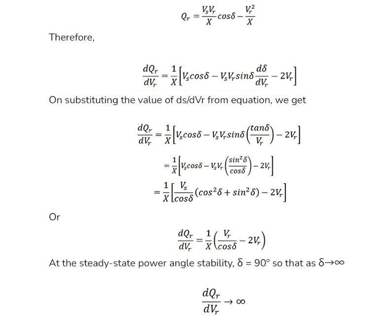
The reactive power expression at the receiving-end bus may be written as

image.png

The above equation represents the steady - state voltage stability limit. It indicates that, at the steady - state stability limit, the reactive power approaches infinity. This implies that the derivative dQ/dVr becomes zero. Thus, the rotor angle stability limit under steady - state conditions coincides with the steady - state voltage stability limit. Additionally, the steady - state voltage stability is also influenced by the load.

Give a tip and encourage the author!
Recommended
What Are the Factors Influencing the Impact of Lightning on 10kV Distribution Lines?
1. Induced Lightning OvervoltageInduced lightning overvoltage refers to the transient overvoltage generated on overhead distribution lines due to nearby lightning discharges, even when the line is not directly struck. When a lightning flash occurs in the vicinity, it induces a large amount of charge on the conductors—opposite in polarity to the charge in the thundercloud.Statistical data shows that lightning-related faults caused by induced overvoltages account for approximately 90% of total fau
Echo
11/03/2025
THD Measurement Error Standards for Power Systems
Error Tolerance of Total Harmonic Distortion (THD): A Comprehensive Analysis Based on Application Scenarios, Equipment Accuracy, and Industry StandardsThe acceptable error range for Total Harmonic Distortion (THD) must be evaluated based on specific application contexts, measurement equipment accuracy, and applicable industry standards. Below is a detailed analysis of key performance indicators in power systems, industrial equipment, and general measurement applications.1. Harmonic Error Standar
Edwiin
11/03/2025
How Vacuum Tech Replaces SF6 in Modern Ring Main Units
Ring main units (RMUs) are used in secondary power distribution, directly connecting to end-users such as residential communities, construction sites, commercial buildings, highways, etc.In a residential substation, the RMU introduces 12 kV medium voltage, which is then stepped down to 380 V low voltage through transformers. The low-voltage switchgear distributes electrical energy to various user units. For a 1250 kVA distribution transformer in a residential community, the medium-voltage ring m
James
11/03/2025
What Are the Handling Procedures After Transformer Gas (Buchholz) Protection Activation?
What Are the Handling Procedures After Transformer Gas (Buchholz) Protection Activation?When the transformer gas (Buchholz) protection device operates, a thorough inspection, careful analysis, and accurate judgment must be carried out immediately, followed by appropriate corrective actions.1. When the Gas Protection Alarm Signal is ActivatedUpon activation of the gas protection alarm, the transformer should be inspected immediately to determine the cause of operation. Check whether it was caused
Felix Spark
11/01/2025
Related Products
Send inquiry
Download
Get the IEE Business Application
Use the IEE-Business app to find equipment, obtain solutions, connect with experts, and participate in industry collaboration anytime, anywhere—fully supporting the development of your power projects and business.