What is overload protector?

An overload protector is an electrical device designed to protect circuits and electrical equipment from damage caused by overload currents. Overload refers to a situation where the current in a circuit exceeds its rated value for an extended period, but has not yet reached the level of a short circuit. The overload protector detects the current in the circuit and disconnects it when the current exceeds a preset threshold, thereby preventing overheating, damage, or fires.
Working Principle
Overload protectors typically detect and respond to overload conditions through one of the following methods:
Thermal Protection:
Bimetallic Strip: Uses a bimetallic strip (made of two metals with different thermal expansion coefficients) to detect temperature. When the current is too high, the bimetallic strip deforms due to the increased temperature, triggering the disconnect mechanism.
Thermomagnetic Protection: Combines thermal and magnetic effects, using both a thermal sensor and a magnetic sensor to detect overload.
Electromagnetic Protection:
Electromagnetic Trip Unit: Utilizes an electromagnet to detect overload current. When the current exceeds the preset value, the electromagnet attracts the trip mechanism, disconnecting the circuit.
Electronic Protection:
Microprocessor Control: Uses a microprocessor or integrated circuit to monitor the current. When the current exceeds the set value, it triggers an electronic switch to disconnect the circuit.
Types
Thermal Overload Relay:
Commonly used for motor protection, it detects the current in the motor to prevent overheating. Thermal overload relays can be used independently or in conjunction with contactors.
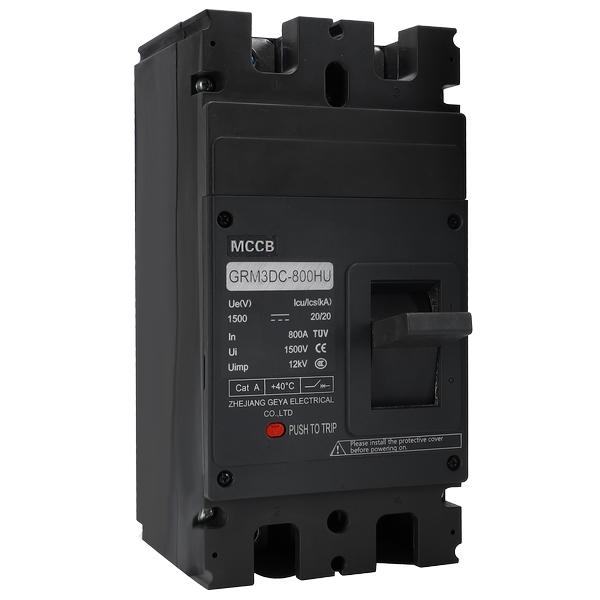
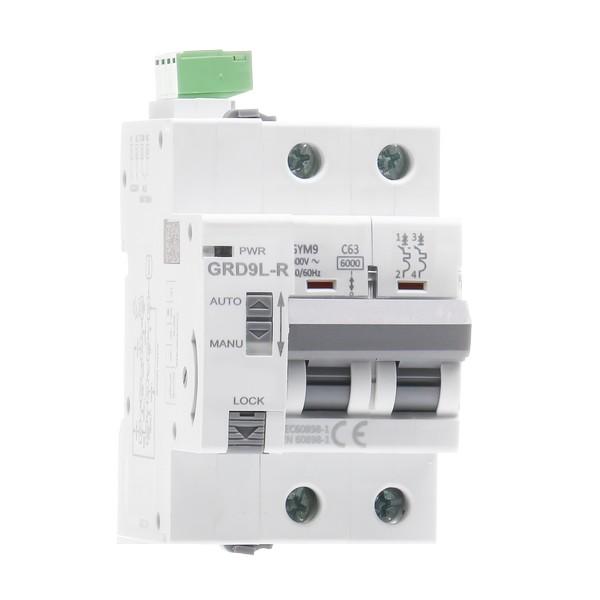
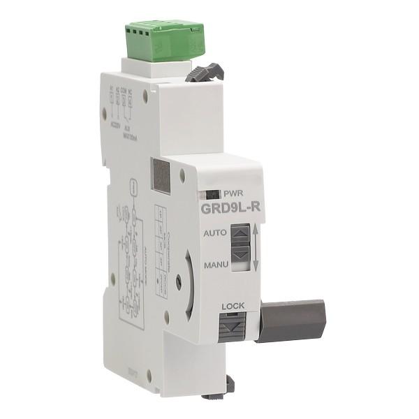
Circuit Breaker:
A multifunctional protection device that not only protects against overload but also against short circuits and transient high currents. Circuit breakers are typically available in thermal-magnetic and electronic types.
Fuses:
A one-time protection device that melts a metal wire inside when the current exceeds its rated value, disconnecting the circuit. Fuses are suitable for low-voltage and low-current circuits.
Applications
Overload protectors are widely used in various electrical systems and equipment, including but not limited to:
Residential Circuits: Protecting home circuits from overload and short circuits.
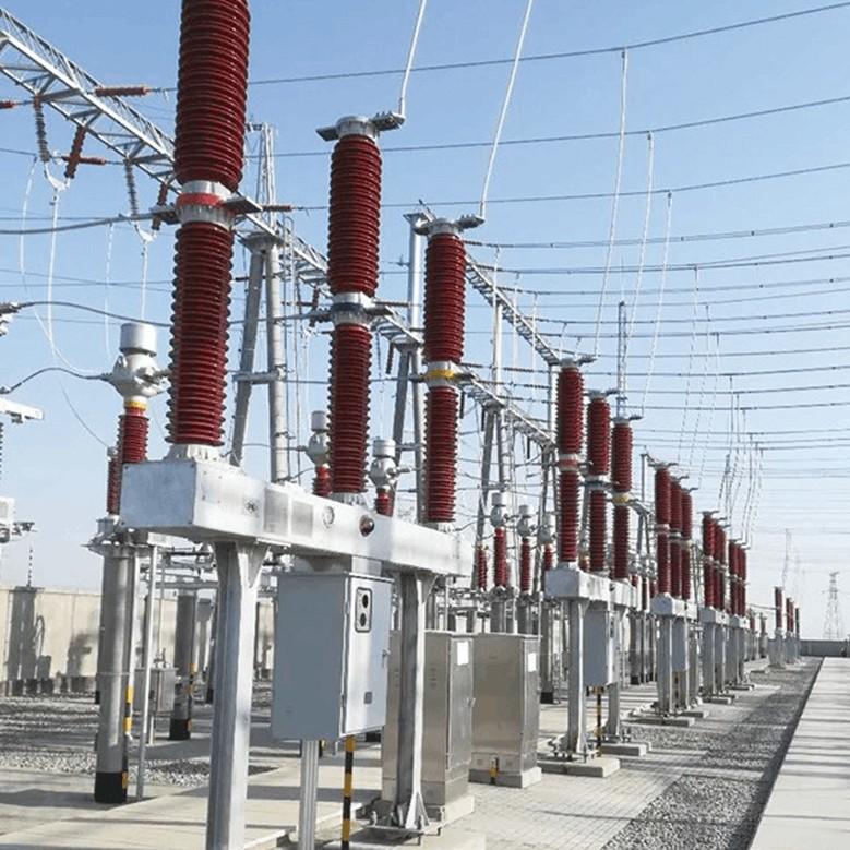
Industrial Equipment: Protecting large equipment such as motors, generators, and transformers.
Distribution Systems: Protecting distribution lines and substation equipment.
Electronic Devices: Protecting the power supply sections of electronic devices to prevent overheating and damage.
Selection and Installation
When choosing an appropriate overload protector, consider the following factors:
Rated Current: The rated current of the protector should match the rated current of the protected circuit.
Response Time: The protector should disconnect the circuit after the overload current has persisted for a certain period, rather than immediately, to avoid false trips.
Environmental Conditions: Consider the temperature, humidity, and contamination levels of the installation environment and choose a suitable protector.
Certification and Standards: Select protectors that comply with relevant international and national standards, such as IEC and UL.
Summary
An overload protector is an essential safety device in electrical systems, detecting and responding to overload currents to protect circuits and equipment from damage. Proper selection and installation of overload protectors can significantly enhance the safety and reliability of electrical systems.