• Product
  • Suppliers
  • Manufacturers
  • Solutions
  • Free tools
  • Knowledges
  • Experts
  • Communities
Search


Solving the Contradiction in Arc Suppression Coil Grounding: Damping Resistor Applications and Tuning Strategies

Edwiin
Edwiin
Field: Power switch
China

Contradiction Points

In automatic tracking arc suppression coils, the adjustment precision is high, the residual current is small, and the operation is close to the resonance point.

In an automatic tracking arc suppression coil grounding system, two factors must be considered:

  • Under normal operating conditions, the long-term voltage displacement of the neutral point should not exceed 15% of the system's nominal phase voltage;

  • In the case of a ground fault, the grounding residual current should be small to facilitate arc extinction.

As the tuning requirements for an arc suppression coil grounding system, it is necessary to ensure that the neutral point displacement voltage does not exceed 15% of the rated phase voltage during normal operation, while also making the detuning degree as small as possible. This is obviously contradictory.

Solution Points

Currently, a damping resistor is connected to the circuit of the automatic compensation arc suppression coil to resolve this contradiction.

During normal operation of the power grid, due to the presence of the damping resistor, the damping rate d of the resonant circuit increases significantly. Even if the detuning degree is 0 at this time, the neutral point displacement voltage can basically be controlled within the range specified by regulations.

When a ground fault occurs in the power grid, the damping resistor is short-circuited, so that the grounding residual current can be well compensated, basically resolving the contradiction between small grounding residual current and excessive neutral point displacement voltage beyond the specified range.

To prevent series resonance overvoltage, a damping resistor is added to the arc suppression coil grounding circuit to suppress the generation of resonance overvoltage, ensuring that the neutral point displacement voltage does not exceed 15% of the phase voltage during normal operation of the system.

Analysis Points

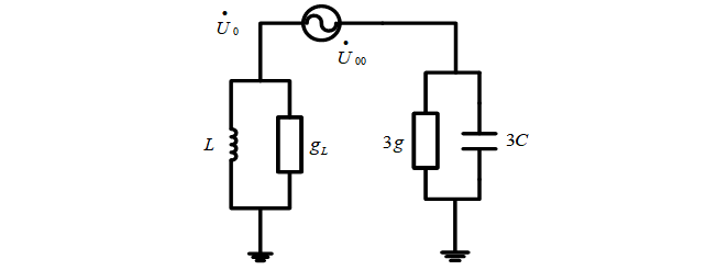
During normal operation of the power grid, the zero-sequence equivalent circuit of the power grid grounded via an arc suppression coil is a series resonant circuit, as shown in the following figure. In the figure, L and gₗ are the inductance and equivalent conductance of the arc suppression coil; C and g are the per-phase-to-ground capacitance and leakage conductance of the power grid; U₀₀ is the asymmetric voltage.

The neutral point displacement voltage derived from the above figure is:

To meet the requirements of regulations, the method of increasing the detuning degree ν to keep the system away from the resonance point is often adopted. However, as can be seen from the above formula, besides increasing the detuning degree ν, the method of increasing the damping rate d can also be used. Connecting a damping resistor in parallel or in series with the arc suppression coil aims to increase the damping rate of the power grid, thereby reducing the neutral point displacement voltage U0. When a ground fault occurs in the power grid, short-circuiting the damping resistor allows the ground residual current to be well compensated.

Key Points for Attention

To add a damping resistor, the forms of connecting the damping resistor in series with the arc suppression coil circuit or in parallel on the secondary side of the arc suppression coil can be adopted. When a single-phase ground fault occurs in the system, the neutral point voltage rises and the neutral point current increases. When the current exceeds the set value, the damping resistor should be quickly short-circuited to avoid burning it out. When the system returns to normal, the short-circuit point of the damping resistor should be disconnected in a timely manner, so that the damping resistor is normally connected in series to the arc suppression coil circuit again. Otherwise, the system may experience resonance overvoltage due to the loss of the damping resistor.

Give a tip and encourage the author!
Recommended
How to Identify Internal Faults in a Transformer?
Measure DC resistance: Use a bridge to measure the DC resistance of each high- and low-voltage winding. Check whether the resistance values among phases are balanced and consistent with the manufacturer’s original data. If phase resistance cannot be measured directly, line resistance may be measured instead. The DC resistance values can indicate whether the windings are intact, whether there are short circuits or open circuits, and whether the contact resistance of the tap changer is normal. If
Felix Spark
11/04/2025
THD Measurement Error Standards for Power Systems
Error Tolerance of Total Harmonic Distortion (THD): A Comprehensive Analysis Based on Application Scenarios, Equipment Accuracy, and Industry StandardsThe acceptable error range for Total Harmonic Distortion (THD) must be evaluated based on specific application contexts, measurement equipment accuracy, and applicable industry standards. Below is a detailed analysis of key performance indicators in power systems, industrial equipment, and general measurement applications.1. Harmonic Error Standar
Edwiin
11/03/2025
Busbar-Side Grounding for 24kV Eco-Friendly RMUs: Why & How
Solid insulation assistance combined with dry air insulation is a development direction for 24 kV ring main units. By balancing insulation performance and compactness, the use of solid auxiliary insulation allows passing insulation tests without significantly increasing phase-to-phase or phase-to-ground dimensions. Encapsulation of the pole can address the insulation of the vacuum interrupter and its connected conductors.For the 24 kV outgoing busbar, with the phase spacing maintained at 110 mm,
Dyson
11/03/2025
How Vacuum Tech Replaces SF6 in Modern Ring Main Units
Ring main units (RMUs) are used in secondary power distribution, directly connecting to end-users such as residential communities, construction sites, commercial buildings, highways, etc.In a residential substation, the RMU introduces 12 kV medium voltage, which is then stepped down to 380 V low voltage through transformers. The low-voltage switchgear distributes electrical energy to various user units. For a 1250 kVA distribution transformer in a residential community, the medium-voltage ring m
James
11/03/2025
Related Products
Send inquiry
Download
Get the IEE Business Application
Use the IEE-Business app to find equipment, obtain solutions, connect with experts, and participate in industry collaboration anytime, anywhere—fully supporting the development of your power projects and business.