• Product
  • Suppliers
  • Manufacturers
  • Solutions
  • Free tools
  • Knowledges
  • Experts
  • Communities
Search


5 Common Transmission Line Faults and Effective Prevention Methods

Edwiin
Field: Power switch
China

1. Overview

A transmission line fault is a sudden power interruption caused by various factors. To restore supply and prevent recurrence, operators must first locate the fault point, identify the type, determine the cause, and implement repairs.

The most common faults include:

  • Lightning strikes

  • Ice buildup (icing)

  • Wind deviation (wind sway)

  • Bird-related issues

  • Pollution flashover

  • External damage

Understanding these faults and their prevention is critical for grid reliability.

2. Lightning Strike Faults

Lightning is a powerful atmospheric discharge from charged thunderclouds. For transmission lines, it causes two main hazards:

  • Direct strikes: Hit conductors, ground wires, or towers, causing high currents and flashovers.

  • Induced surges: Occur when lightning strikes nearby, inducing high voltages on lines, leading to insulation breakdown.

Causes

Lightning can cause tripping, equipment damage, outages, and even widespread blackouts—especially in high-lightning areas.

Prevention Measures

  • Install shield wires with reduced protection angles

  • Lower tower grounding resistance

  • Use coupling ground wires or buried conductors

  • Install line surge arresters

  • Apply differential insulation or arc protection (e.g., arc horns, parallel gaps)

  • Enhance insulation levels

  • Use automatic reclosing to restore power after transient faults

  • Install pre-discharge rods or negative-angle needles

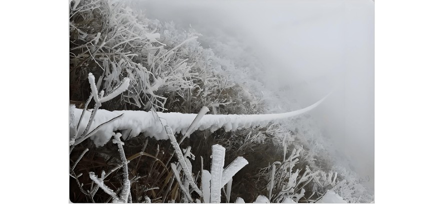
3. Ice Buildup (Icing) Faults

Icing occurs in cold, wet conditions (–5°C to 0°C) with fog or drizzle, forming glaze ice. Repeated freeze-thaw cycles create dense mixed ice, leading to heavy accumulation on conductors.

Ice typically forms on the windward side and may cause conductor twisting, resulting in circular or elliptical shapes.

Ice Buildup (Icing) Faults.jpg

Causes

Climate change has increased extreme weather, making icing a major threat. It can cause:

  • Mechanical overloading

  • Galloping (aerodynamic instability)

  • Ice flashover

  • Uneven de-icing jumps

  • Broken conductors or collapsed towers

Prevention Strategies: Avoid, Resist, Modify, Prevent, De-ice

  • Route lines away from icing-prone areas (e.g., lakes, high altitudes, wind corridors)

  • Reduce span lengths and tension section length

  • Strengthen towers and ground wire supports

  • Use anti-icing conductors (e.g., high-strength ACSR)

  • Install armor rods for mechanical protection

  • Use V-string or double suspension insulators to prevent ice bridging

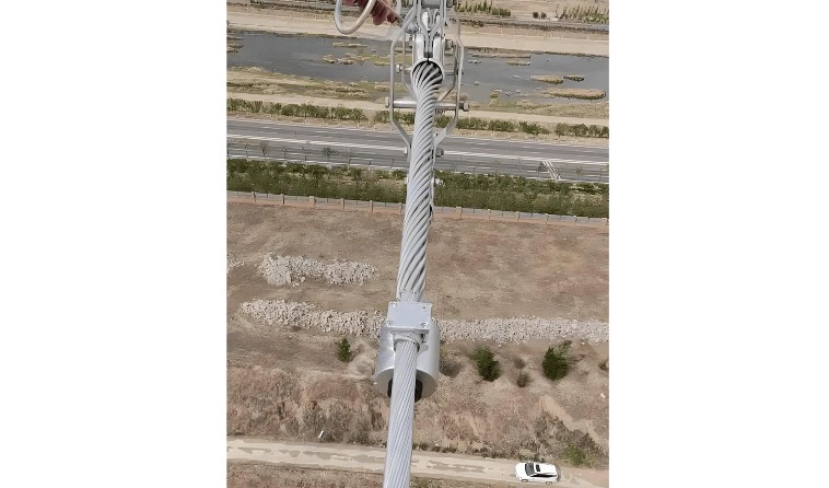
4. Wind Deviation (Wind Sway) Faults

Wind deviation is the lateral movement of conductors or insulators under wind load, reducing air clearance and causing flashover—especially on jumper wires or suspension strings.

Wind Deviation (Wind Sway) Faults.jpg

Types

  • Jumper swing on angle towers

  • Insulator string tilt under wind pressure

  • Conductor-to-conductor or conductor-to-tower clearance reduction

Insulator string sway is the leading cause of wind-induced tripping.

Causes

  • Design limitations: Many lines are rated for 30 m/s winds, underestimating microclimate or localized high-wind zones (e.g., canyons, ridges).

  • Strong localized winds: Typhoons, downbursts, or gusts increase conductor displacement and electric field stress at sharp hardware points.

  • Rain effects: Wind-driven rain forms conductive water paths, lowering air gap insulation strength.

Prevention Measures

  • Increase tower head clearance and design safety margins

  • Reduce spans and conductor sag

  • Add weights (dampers) to insulator strings

  • Use V-string or double-string configurations

  • Install wind-resistant guy wires or external tension cables

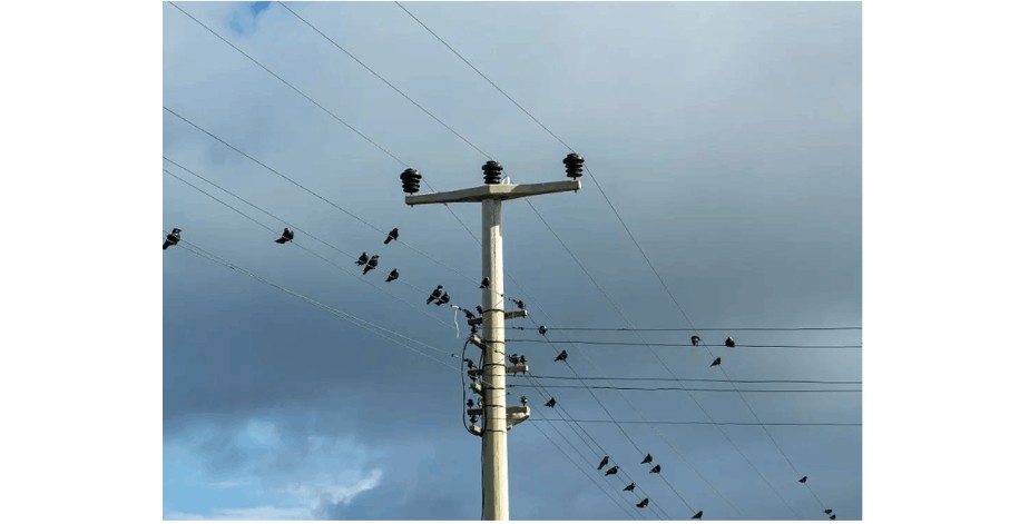
5. Bird-Related Faults

Bird-related faults occur when birds nesting, defecating, or flying near lines cause flashovers or equipment damage.

Bird-Related Faults.jpg

Fault Types

  • Nest-related: Long nesting materials bridge conductors and towers.

  • Dropping-related: Droppings reduce insulator insulation, causing flashover.

  • Bird-body short circuits: Large birds bridge phases or conductor-to-ground.

  • Pecking damage or collision faults

  • Secondary faults from nesting debris

Causes

  • Nesting materials creating conductive paths

  • Conductive bird droppings on insulators

  • Birds perching or flying near energized parts

Prevention Measures

  • Route new lines ≥5 km from bird habitats and avoid flight corridors

  • Install physical deterrents:

    • Bird guards, nest blockers, spikes, shields

    • Large-diameter or bird-safe insulators

    • Insulator covers and waterproof barriers

  • Use active repellents:

    • Sonic, visual, or intelligent sound-and-light bird scarers

  • Provide alternatives:

    • Install artificial nests or bird perches away from equipment

Give a tip and encourage the author!
Recommended
Relay Protection Basics: Types of Transmission Line Faults and Fundamental Protection Schemes
1. Types of Faults on Power LinesPhase-to-Phase Faults: Three-phase short circuit Two-phase short circuitGround Faults: Single-phase to ground fault Two-phase to ground fault Three-phase to ground fault2. Definition of Relay Protection DevicesWhen an abnormality or fault occurs in a component of a power system, relay protection devices are those that can quickly and selectively isolate the faulty or abnormal component from the system, ensuring the continued normal operation of the remaining heal
Leon
09/05/2025
Strange Devices on Transmission Lines: 5 Little-Known Practical Functions(1)
1 Aviation Warning SpheresAviation warning spheres, also known as reflective safety spheres, are used on overhead transmission lines near airports, especially on extra-high-voltage (above 220kV) lines and river-crossing transmission lines. Highly visible aviation marker spheres (aviation warning spheres) must be installed along the lines to provide warning signals.The aviation marker sphere (aviation warning sphere) has a diameter of ф=600mm. The sphere can be manufactured in various bright colo
Leon
09/04/2025
Transmission Line
In transmission lines, a "π" connection involves breaking the original line from Substation A to Substation B and inserting Substation C, forming a "π" configuration. After the "π" connection, the original single line is divided into two independent transmission lines. Following the "π" connection, Substations B and C may both be powered by Substation A (in this case, Substation C receives power via a feeder from Substation B's busbar, or possibly from another voltage point within Substation B);
Encyclopedia
09/04/2025
What are the principles of forced re-energization of transmission lines?
Principles of Forced Re-energization of Transmission LinesRegulations for Forced Re-energization of Transmission Lines Correctly select the forced re-energization end of the line. If necessary, change the connection configuration before forced re-energization, taking into account the reduction of short-circuit capacity and its impact on grid stability. There must be a transformer with its neutral point directly grounded on the busbar at the forced re-energization end. Pay attention to the impact
Edwiin
09/04/2025
Seed Inquiry
Download
Get the IEE Business Application
Use the IEE-Business app to find equipment, obtain solutions, connect with experts, and participate in industry collaboration anytime, anywhere—fully supporting the development of your power projects and business.