• Product
  • Suppliers
  • Manufacturers
  • Solutions
  • Free tools
  • Knowledges
  • Experts
  • Communities
Search


Revolutionizing Hydraulics with a New Transformer

Noah
Noah
Field: Design & Maintenance
Australia

1. About the Hydraulic Transformer

A hydraulic system typically consists of a hydraulic power source (pump), actuators (hydraulic cylinder or motor), control components, and auxiliary parts. However, one critical component is notably missing—the hydraulic transformer. Hydraulic transmission is often compared to electrical transmission, and hydraulic control systems to electrical control systems, due to their strong similarities and corresponding functional components and parameters. Can we imagine an electrical system without transformers? Similarly, the hydraulic transformer is undoubtedly an essential and indispensable component for hydraulic transmission and control systems.

Establishing a constant-pressure hydraulic network, building large-scale hydraulic systems and subsystems, enabling independent control of multiple loads, and achieving mechatronic-hydraulic integration are inevitable trends in modern hydraulic technology. The hydraulic transformer will be widely adopted in hydraulic systems and become a key hydraulic component.

Currently, both "conventional" and "novel" types of hydraulic transformers exist in research, but they remain in the experimental stage domestically and internationally, with no mature, industrial-grade products meeting market demands. Their design concepts and applications primarily focus on pressure regulation with very limited adjustment range, making "pressure regulator" a more accurate term than "hydraulic transformer."

A patented technology introduces a new type of hydraulic transformer that surpasses existing designs. By using a high-speed rotating rotor, it achieves continuous and stable pressure amplification and reduction, fulfilling the conceptual definition, functional requirements, and practical roles of a true "transformer." The application of this new hydraulic transformer will enable the creation of high-quality, multi-pressure constant-pressure circuits in hydraulic systems. Parameters such as "rated pressure," "rated power," "rated displacement," and "rated torque" of hydraulic components will gain clear practical significance. This provides advanced methods and convenient tools for component selection, system design, functional matching, efficiency improvement, and equipment monitoring and diagnostics.

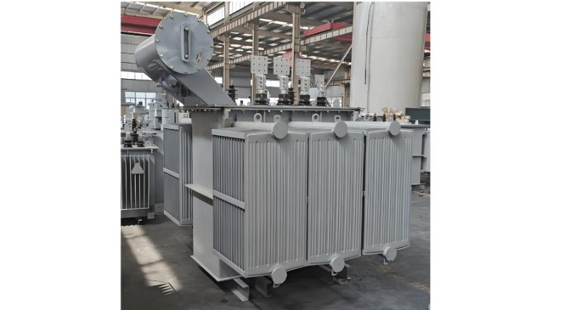
transformer...jpg

In short, this patented "hydraulic transformer" fills a critical gap in hydraulic technology and component markets, and is poised to drive transformative technological progress in the field of hydraulics.

The Patent: "A Hydraulic Transformer" 

Technical Advantages of the Hydraulic Transformer:

  • Simple structure, compact size, lightweight

  • Low rotational inertia, fast response, high sensitivity

  • Large transformation ratio, stable and unaffected by system parameter fluctuations

  • Capable of both step-up and step-down pressure conversion, enabling pressure energy recovery

  • Secondary flow adjustable from 0 to maximum rated flow

  • Effective isolation between primary and secondary working media

  • Near-zero static loss, low dynamic power loss

  • Easy installation and maintenance-free operation

2. Application and Promotion of the Hydraulic Transformer

Conventional hydraulic systems are often load-sensing systems, which rely on numerous control valves, resulting in complex configurations and significant throttling losses. The pump and actuators are difficult to match optimally, and multiple actuators suffer from pressure coupling. Often, multiple pumps are required to supply different actuators. In contrast, a constant-pressure network offers high adaptability and efficiency. The hydraulic transformer is essential in such networks because it can:

  • Generate output pressure higher than the source pressure

  • Effectively decouple the load from the energy source, making load performance independent of source dynamics

  • Drive multiple loads at different pressure levels simultaneously

  • Enable independent control of multiple loads directly at the user end

  • Simplify system design, reduce manufacturing costs, and minimize throttling losses

The adoption of constant-pressure networks and modular design represents the inevitable direction of modern hydraulic technology, and the hydraulic transformer is the key enabler.

The hydraulic transformer not only transmits power but also transforms pressure and flow parameters, while providing isolation between primary and secondary media. As such, various liquid media—mineral oil, water, seawater, organic fluids, biofluids—can coexist in the same system while remaining isolated, enabling energy exchange. This makes the hydraulic transformer highly applicable in environmentally friendly, green, energy-saving, and pollution-control fields.

Moreover, the hydraulic transformer can recover energy from loads, especially those with potential energy (e.g., lifting mechanisms), making its energy-saving and environmental benefits undeniable. Upon closer examination of its structure and operational characteristics, it becomes evident that the hydraulic transformer can collect, concentrate, amplify, and transmit dispersed, weak, or disordered energy, transforming it into a usable and recoverable form.

It holds great potential in emerging green energy applications such as:

  • Recovery of residual energy from wastewater and exhaust gases

  • Utilization of low-head hydropower

  • Wind energy harvesting

More importantly, the hydraulic transformer enables the construction of a unified fluid power and control network that integrates liquid and gas phases with isolation and parameter conversion. Fluid power technology includes two branches: hydraulics (liquid) and pneumatics (gas), traditionally separated due to differences in medium and operating parameters. However, integrating them into a single network is now feasible.

By using the hydraulic transformer (which could later be renamed a "fluid pressure transformer") to isolate media and adjust parameter levels, hydraulics and pneumatics can be unified into a single fluid power network. This aligns with the evolving needs of modern manufacturing and market demands.

Existing technologies already demonstrate this potential:

  • Pneumatic-hydraulic intensifiers

  • Pneumatic-hydraulic valves

  • Hydraulic hammers

Though these are standalone applications, they highlight the complementary advantages of combining hydraulic and pneumatic technologies.

For example, in the rapidly advancing field of intelligent robotics, integrating hydraulic and pneumatic systems could dramatically improve robots’ ability to mimic human motion. When AlphaGo can elegantly play Go with physical hands, only then can it truly be called a "man vs. machine" showdown—not an exaggeration, but a reflection of market demand for technological advancement.

The emergence of the hydraulic transformer will drive the integration of pneumatic and hydraulic systems, enabling a new unified fluid power and control network. In this network:

  • Pneumatic components’ strengths—fast response, cushioning, elastic force retention—are combined with

  • Hydraulic components’ strengths—high power density, precision, fast transient response—
    resulting in synergistic performance.

It is foreseeable that in the near future, a wide range of new components will emerge, forming integrated and modular units. Alongside the widespread adoption of the hydraulic transformer (or "fluid pressure transformer"), these systems will permeate various sectors of modern manufacturing.

Give a tip and encourage the author!
Recommended
Why is it difficult to increase the voltage level?
The solid-state transformer (SST), also known as a power electronic transformer (PET), uses voltage level as a key indicator of its technological maturity and application scenarios. Currently, SSTs have reached voltage levels of 10 kV and 35 kV on the medium-voltage distribution side, while on the high-voltage transmission side, they remain in the stage of laboratory research and prototype validation. The table below clearly illustrates the current status of voltage levels across different appli
Echo
11/03/2025
Standards and Calculation of LTAC Test for Power Transformers
1 IntroductionAccording to the provisions of the national standard GB/T 1094.3-2017, the primary purpose of the line terminal AC withstand voltage test (LTAC) for power transformers is to evaluate the AC dielectric strength from the high-voltage winding terminals to ground. It does not serve to assess inter-turn insulation or phase-to-phase insulation.Compared with other insulation tests (such as full lightning impulse LI or switching impulse SI), the LTAC test imposes a relatively more stringen
Oliver Watts
11/03/2025
What Are the Handling Procedures After Transformer Gas (Buchholz) Protection Activation?
What Are the Handling Procedures After Transformer Gas (Buchholz) Protection Activation?When the transformer gas (Buchholz) protection device operates, a thorough inspection, careful analysis, and accurate judgment must be carried out immediately, followed by appropriate corrective actions.1. When the Gas Protection Alarm Signal is ActivatedUpon activation of the gas protection alarm, the transformer should be inspected immediately to determine the cause of operation. Check whether it was caused
Felix Spark
11/01/2025
Fluxgate Sensors in SST: Precision & Protection
What is SST?SST stands for Solid-State Transformer, also known as Power Electronic Transformer (PET). From the perspective of power transmission, a typical SST connects to a 10 kV AC grid on the primary side and outputs approximately 800 V DC on the secondary side. The power conversion process generally involves two stages: AC-to-DC and DC-to-DC (step-down). When the output is used for individual equipment or integrated into servers, an additional stage to step down from 800 V to 48 V is require
Echo
11/01/2025
Related Products
Send inquiry
Download
Get the IEE Business Application
Use the IEE-Business app to find equipment, obtain solutions, connect with experts, and participate in industry collaboration anytime, anywhere—fully supporting the development of your power projects and business.