1 Introduction
According to the provisions of the national standard GB/T 1094.3-2017, the primary purpose of the line terminal AC withstand voltage test (LTAC) for power transformers is to evaluate the AC dielectric strength from the high-voltage winding terminals to ground. It does not serve to assess inter-turn insulation or phase-to-phase insulation.
Compared with other insulation tests (such as full lightning impulse LI or switching impulse SI), the LTAC test imposes a relatively more stringent evaluation on the main insulation strength between the high-voltage winding terminals, high-voltage lead terminals, and grounded metallic components such as clamping structures, riser units, and the tank, due to its longer duration (typically 30 seconds for 50 Hz transformers and 36 seconds for 60 Hz transformers).
Numerous insulation test failure cases have shown that many power transformers can withstand lightning impulse (LI) and switching impulse (SI) tests but still experience breakdown during the line terminal AC withstand voltage test (LTAC), with breakdowns often occurring in the final few seconds of the test. This clearly demonstrates the critical importance of test duration in evaluating main insulation and highlights the rigorous nature of the LTAC test in assessing main insulation strength.
Therefore, it is essential for transformer design engineers to accurately calculate the winding potential distribution during the line terminal AC withstand voltage test (LTAC) at the design stage, so as to carry out scientific and rational main insulation design, ensuring sufficient insulation margin from the design source.
2 Interpretation of Standards
The line terminal AC withstand voltage test (LTAC) for power transformers is a newly added high-voltage insulation test item introduced in the latest national standard GB/T 1094.3-2017. It evolved and separated from the short-time induced withstand voltage test (ACSD) specified in the previous standard GB/T 1094.3-2003. The relevant provisions regarding the LTAC test are listed in the table below:
Maximum Equipment Voltage (kV) |
Um≤72.5 |
72.5<Um≤170 |
Um>170 |
Insulation Level Type |
Uniform |
Uniform |
Grade |
Graded、Uniform |
Line - end AC Withstand Test (LTAC) |
N/A |
Special |
Routine |
Special |
Note 1: With mutual agreement between the manufacturer and the user, the LTAC test for power transformers with a highest voltage of equipment ≤ 170 kV may be replaced by a switching impulse (SI) test at the line terminal.
Note 2: For tap-changer insulated power transformers, the LTAC test shall be performed phase by phase. |
The standard provides the following interpretation of the line terminal AC withstand voltage test (LTAC) for power transformers:
For power transformers with Um ≤ 72.5 kV, which are all fully insulated, the main insulation strength between the high-voltage winding and high-voltage lead terminals and ground can be fully evaluated by the applied voltage test (AV). Therefore, the LTAC test is not required.
For power transformers with 72.5 < Um ≤ 170 kV:
If fully insulated, although the main insulation strength can still be adequately verified by the applied voltage test (AV), the LTAC test is specified as a special test. This means it is generally not required during routine testing, but must be performed if explicitly requested by the user.
If neutrally grounded (graded insulation), the LTAC test is specified as a routine test and must be carried out on every unit during factory acceptance tests. However, with user agreement, it may be replaced by a line terminal switching impulse test (SI).
For power transformers with Um > 170 kV, whether fully insulated or graded insulation, the LTAC test is classified as a special test—generally not mandatory unless specifically required by the user. In this case, however, it cannot be replaced by a line terminal switching impulse test (SI).
In practice, for fully insulated power transformers, regardless of voltage level, the line terminal AC withstand voltage test (LTAC) is never performed, because the main insulation strength between the high-voltage winding/lead terminals and ground can be more rigorously verified by the routine 1-minute applied voltage test (AV).
It should be noted that for power transformers with Um > 170 kV, the LTAC test cannot be substituted by the SI test. Both theoretical calculations and historical experience show that for evaluating the main insulation from line terminal to ground in transformers above 170 kV, the LTAC test is approximately 10% more stringent than the SI test.
3 Calculation Method
The purpose of performing the line terminal AC withstand voltage test (LTAC) on a power transformer is to induce the specified test voltage at the high-voltage terminal, while ensuring the low-voltage terminal reaches a voltage value as close as possible to the specified level. There are no mandatory requirements regarding the specific test method. The most common LTAC test method is the "opposite-phase shorted and grounded support method." This section briefly introduces this method using the SZ18-100000/220 power transformer as an example.
3.1 Transformer Parameters
Voltage ratio: 230 ± 8 × 1.25% / 37 kV
Capacity ratio: 100 / 100 MVA
Rated frequency: 50 Hz
Vector group: YNd11
Insulation levels: LI950 AC395 – LI400 AC200 / LI200 AC85
3.2 Test Circuit
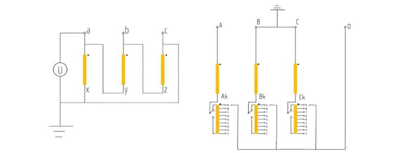
The circuit diagram for the line terminal AC withstand voltage test (LTAC) of this power transformer is shown below:
LTAC Test Circuit Diagram (Phase A as Example)
High-voltage side at tap 9, low-voltage side energized at 2.0 times rated voltage

The key points of the LTAC test circuit are as follows:
The LTAC test shall be performed phase by phase, i.e., a single-phase induced overvoltage test with an induction factor of approximately 2 times the rated voltage. In some cases, it may not be precisely possible to achieve exactly 2 times, and minor deviations are permitted.
Taking the LTAC test on phase A of the high-voltage winding as an example: a certain voltage Uax is applied across the low-voltage terminals ax, with terminal x grounded; terminals b and c on the low-voltage side are left floating. On the high-voltage side, terminals B and C are shorted together and grounded, while terminal A and the neutral (0) terminal are left open (unconnected).
The high-voltage winding must be set at a specific designated tap position to ensure that the required test voltage of 395 kV (with an allowable deviation of ±3%) is induced at the high-voltage line terminal A.
3.3 Calculation Process
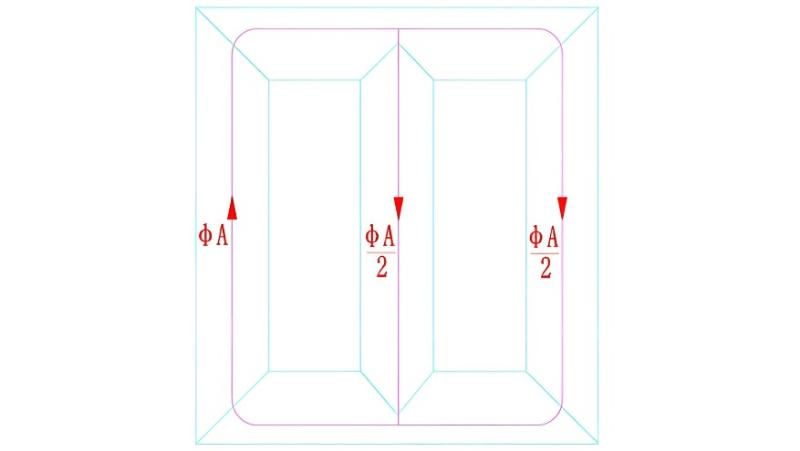
According to Faraday's law of electromagnetic induction and the principle of magnetic flux continuity, under the above test configuration, the magnetic flux in the core limbs of phases B and C is equal to half of that in phase A’s core limb, and in the opposite direction. Therefore, the induced voltage in the windings of phases B and C will have an amplitude equal to half of the induced voltage in phase A.
Schematic Diagram of Core Flux Distribution during LTAC Test
(High-voltage Phase A as Example)

Let the induction factor of the excitation voltage on the low-voltage phase a be K, and let the high-voltage side be at tap position N. The following equation can be established:
Uₐ₀ + U₀₈ = 395
(Since phase B is grounded, Uᵦ = 0)
Given that the amplitude of the magnetic flux in the core limb of phase B is half that of phase A, it follows that:
U₀₈ = ½ Uₐ₀
Therefore:
1.5 × Uₐ₀ = 395
Substituting the transformer's voltage ratio and tap settings:
(230 / 1.732) × [1 + (9 − N) × 1.25%] × K × 1.5 = 395
This equation contains two unknowns, N and K, and thus theoretically has infinitely many solutions. However, from a physical standpoint, both variables are constrained: N must be an integer between 1 and 17, and K is approximately equal to 2.
Solving the equation with N = 9 yields K = 1.98.
Alternatively, setting K = 2 and N = 9 gives an induced voltage Uₐ = 398.4 kV.
Using the above formula, the induced ground potential at any point on the transformer windings during the LTAC test can be calculated.
3.4 Voltage Distribution
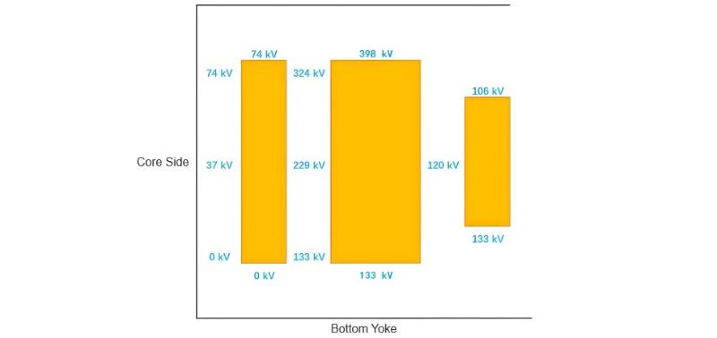
Using the above calculation method, the potential distribution across the windings during the LTAC insulation test on phase A of the high-voltage winding can be determined as follows:
Winding Potential Distribution during Single-Phase LTAC Test on Phase A

From the above induced voltage distribution diagram, it can be seen that during a single-phase LTAC test, the induced potential difference between windings is relatively small. Therefore, the LTAC test does not impose a rigorous evaluation—nor does it fully assess—the main insulation strength between windings. However, the evaluation of the main insulation strength from the high-voltage line terminal to ground is the most severe under this test (this conclusion applies specifically to graded-insulation transformers). During design, special attention must be paid to verifying the main insulation strength between the high-voltage winding terminal, the high-voltage lead terminal, and grounded components such as clamping structures, tank walls, and high-voltage bushing risers under LTAC test conditions.


