Transformer Fault Diagnosis: Advanced Testing Methods

Optimized Guide to Transformer Fault Diagnosis and Advanced Testing Techniques
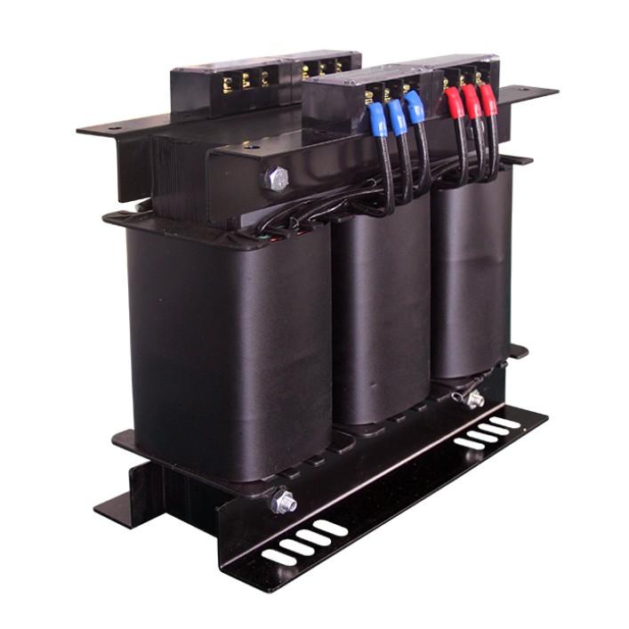
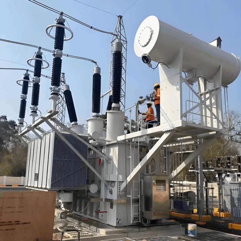
Transformers are core components in power systems, and their operational reliability directly impacts power supply safety. Common types include oil-immersed and dry-type transformers. Failures typically occur in the windings, core, connections, and insulation oil, with typical issues such as inter-turn short circuits, insulation aging, overheated joints, and multi-point core grounding.
1. Common Fault Indicators
Immediate attention is required if a transformer exhibits any of the following symptoms:
Severe overheating or abnormal temperature rise
Unusual noises (e.g., humming, arcing)
Three-phase voltage/current imbalance
Darkened oil color, acidic odor, or sludge formation
Frequent protective relay operations or tripping
2. Routine Maintenance Items
To ensure long-term stable operation, the following basic tests should be performed regularly:

3. Advanced Diagnostic Techniques
1. ALL-Test – Comprehensive Winding Condition Assessment
Principle
Uses high-frequency, low-voltage signals (not high voltage) to excite windings and measure key parameters:
DC Resistance (R)
Impedance (Z)
Inductance (L)
Phase Angle Tangent (tgφ)
Current-to-Frequency Ratio (I/F)
Multi-parameter analysis enables high-sensitivity detection of early winding defects.
Key Advantages
Non-destructive: Low-voltage testing avoids aggravating existing flaws;
High Precision: Resolution up to 0.001Ω, capable of detecting minor inter-turn faults;
Fast On-Site Diagnosis: Internal condition assessed without core lifting;
Trend-Based Monitoring: Data can be stored and trended for predictive maintenance;
Multi-Parameter Cross-Validation: Enhances diagnostic accuracy through parameter correlation.
Evaluation Criteria (Empirical)

Case Comparison

2. Turns Ratio Test (TTR)
Purpose
Verifies actual turns ratio against nameplate value to detect:
Inter-turn short circuits
Open circuits
Wiring errors
Winding deformation
Acceptance Criteria
Deviation > ±0.5%: Requires further investigation;
Unbalanced three-phase ratios: Indicates localized damage;
No reading: Possible severe short or open circuit.
Best Practices
Use dedicated TTR tester (accuracy ≥0.1%);
De-energize and discharge fully before test;
Record all three phases and compare historically.
3. Transformer Oil Quality Testing
For oil-immersed transformers, insulating oil acts as the "lifeblood" — its condition reflects overall equipment health.
Routine Physicochemical Tests

4. Dissolved Gas Analysis (DGA) – The “Gold Standard” of Fault Diagnosis
Principle
Gas chromatography analyzes types and concentrations of dissolved gases in oil to identify fault type and severity — even while energized.
Key Gases and Associated Faults

Judgment Thresholds (by Volume)

4. Recommended Integrated Diagnostic Strategy

5. Summary & Recommendations
Prevention over Repair: Establish regular testing schedules to prevent unexpected failures;
Multi-Method Integration: Combine ALL-Test, DGA, and TTR for cross-validated, reliable diagnosis;
Data-Driven Decisions: Maintain equipment health records and monitor parameter trends;
Smart Upgrades: Consider online monitoring (e.g., continuous DGA, temperature sensors) for predictive maintenance;
Personnel Training: Ensure staff understand basic criteria and emergency response procedures.