What are the technical features and applications of single-phase distribution transformers?

1 Technical Features of Single - phase Transformers
From the operation practice of foreign distribution networks, it is known that single - phase transformers are quite widely applied. Compared with three - phase transformers, they have unique advantages, which are specifically reflected as follows:
1.1 Simple Structure
This characteristic makes that, when using the same materials, for single - phase transformers with the same capacity, their no - load losses are lower than those of three - phase transformers. To a certain extent, they are more able to meet the needs of energy conservation and consumption reduction. Taking the commonly - used transformers with capacities of 100 kVA and 50 kVA as examples, the comparison of various indicators is shown in Table 1.
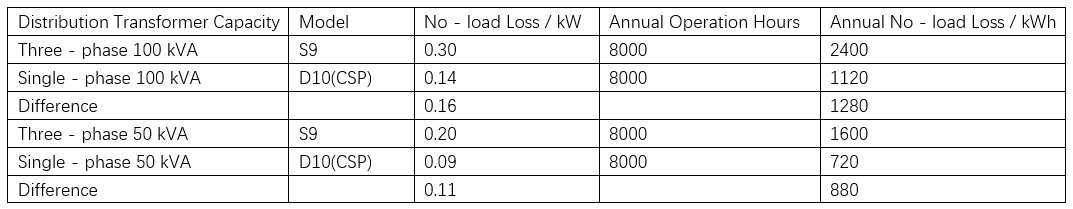
Calculated over 8,000 annual operating hours, a 100 kVA D10 single - phase distribution transformer has 1,280 kWh less no - load loss than an S9 three - phase unit of the same capacity; a 50 kVA one saves 880 kWh. On average, single - phase transformers cut no - load losses by over 50% versus three - phase types.
1.2 Compact & Easy to Install
This lets low - voltage lines reach load points more closely, shrinking the power supply radius and curbing distribution network losses. Low - voltage grid losses once accounted for a large share of total grid losses. Pre - renovation, urban low - voltage overhead line losses ran 7% - 12% (even over 30% in some regions). Post - rural grid upgrades, a 12% comprehensive loss target was set, with cities now approaching it.
Two main causes drive high low - voltage losses: 1) Three - phase transformers for residential/commercial supply keep power sources far from loads, boosting supply radii and line losses; unbalanced currents also add transformer losses. 2) Large radii enable electricity theft, complicating management. Single - phase transformers place power sources near users, slashing supply distances, line losses, and theft risks.
The “small capacity, dense points, short radius” supply model, widely used in low - voltage grids, effectively cuts losses—single - phase transformers are key to implementing this approach.
1.3 Relative Savings in Project Cost
For single - phase transformer power supply, high - voltage branches use two - wire erection, and low - voltage lines use two or three wires. In contrast, three - phase transformers require three - wire high - voltage and four - wire low - voltage erection. Thus, single - phase setups save wires and reduce usage of drop - out fuses, surge arresters, and hardware.Incomplete stats show: single - phase cuts ~10% of high - voltage line costs and 15% of low - voltage line project costs.
1.4 Improved Power Supply Reliability
Single - phase transformers suit small - capacity, dense - point scenarios, boosting user coverage. Statistically, a larger user base lifts reliability coefficients. For management, rationing via single - transformer circuit - pulling narrows outages and lessens reliability impacts. Structurally, three - phase transformers’ integrated coils risk full - transformer outages if one coil fails, causing area blackouts.
Technically, three - phase transformers (Y/Y₀ or △/Y₀) face voltage anomalies in other phases when one fuse blows. Their 380V/220V three - wire four - wire low - voltage systems risk sudden voltage surges from neutral short - circuits, disrupting lighting and damaging equipment. Single - phase transformers largely avoid such issues, ensuring reliability.
2 Applications of Single - phase Transformers
2.1 Scope of Use
Based on the technical characteristics of single - phase transformers, their application is recommended in the following scenarios:
2.1.1 Residential Areas in Urban Communities
Currently, electricity consumption in urban residential areas is mainly for lighting and single - phase power (e.g., household appliances like air conditioners and refrigerators), meeting the requirements for "high - voltage power supply to households". According to housing designs and load distribution, adopt a power supply model of "one single - phase transformer per building" or "one per unit" to minimize the low - voltage network supply radius (ideally within 100 meters), enhancing power supply efficiency and quality.
2.1.2 Rural Lighting and Small - scale Power Use
Rural lighting and small - scale power applications (e.g., small agricultural machinery, irrigation equipment) feature low load and minimal fluctuation, making them suitable for small - capacity single - phase transformers. Proper deployment of such transformers can precisely match load demands, reduce power supply costs, and ensure stable electricity supply.
2.1.3 Communities and Markets with Severe Electricity Theft
Implementing "high - voltage power supply to households" can eliminate electricity theft caused by illegal low - voltage wiring. Additionally, it facilitates line - by - line and transformer - by - transformer line loss assessment, enabling accurate monitoring of power consumption losses and strengthening power management.
2.1.4 Optimization of Power Supply for Small - scale Industrial Users
Promote the transition of small - scale industrial users from "shared transformers" to "dedicated transformers". With the popularization of single - phase transformers, small industrial and commercial users can install dedicated units. Guided by electricity and pricing policies, the adoption of dedicated transformers will become more prevalent, separating residential lighting from three - phase industrial power. Replacing three - phase transformers with single - phase ones where appropriate can reduce losses in public low - voltage lines and shared transformers, balance loads, and improve voltage stability at the user end.
2.2 Issues When Using Single - phase Transformers
Currently, most single - phase distribution transformers use high - quality cold - rolled silicon steel sheets (annealed) as core material, manufactured via wound - core tech. Their no - load/load losses and operating noise are far lower than S9 - type three - phase transformers.
With connection group label I/I₀, there are two main wiring methods:
Three - tap (low - voltage side): A single winding with a middle tap grounded, forming two windings. Voltage ratio: 10 kV/0.22 kV. Wiring: See Figure 1 (a₁, a₂ = phase wires; x = neutral).
Four - tap (low - voltage side): Double windings (no electrical connection between them). Voltage ratio (high - to - low): 10 kV/0.22 kV. Wiring: See Figure 2.
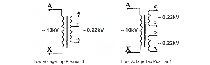
In the figure, a1, a2 are phase wires, and x1, x2, x are neutral wires. When using single - phase transformers, note these:
For power supply, the low - voltage side usually uses a three - wire setup. Take x1/x2/x as the neutral wire (must be reliably grounded). a1 ,a2 (phase wires) can’t be paralleled; evenly distribute loads to minimize neutral current at the low - voltage tap and reduce losses.
For low - voltage supply, use the TT system (neutral switch - controllable) or TN system (neutral non - switch - controllable).
Select the high - voltage tap based on the substation’s 10 kV outlet three - phase currents. Imbalanced currents increase main transformer losses, cause negative - sequence voltage, and risk protection misoperation. Measure 10 kV outlet currents first and set the tap per current balance rules.
Single - phase transformers suit single - phase loads. Survey load composition and layout; separate single - phase and three - phase loads, place transformers near loads to boost efficiency.
Do load forecasting; choose a 20–100 kVA transformer (typical range).
For low - voltage supply, install sectional/tie pole switches (if possible) to improve reliability.


