
Solar photovoltaic power generation, a key form of solar energy use, converts sunlight to electricity via solar cells. Free from resource, material, or environmental limits and eco - friendly, it has broad prospects and is a priority renewable energy tech globally. In grid - connected PV systems, transformers (core energy - conversion gear) are essential. Current step - up transformers for PV mainly use 10 kV/35 kV SC - series epoxy - insulated dry - type units, split into two - winding and double - split types. This paper details their selection.
1 Two - Winding Dry - Type Transformers
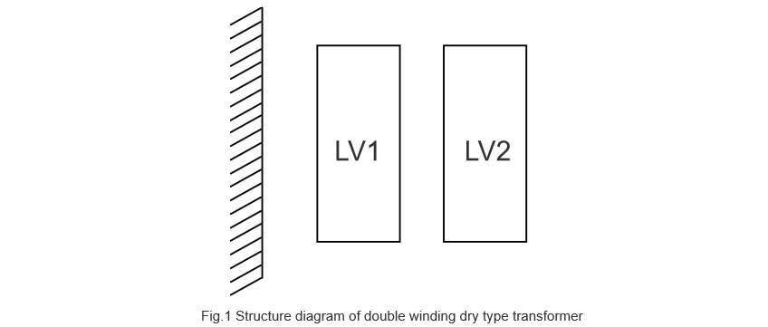
The structure of two - winding dry - type transformers for PV (as in Figure 1, original reference retained) differs little from traditional distribution dry - type ones in design, process, and manufacturing—core difference is their step - up role. Usually, a single inverter gets a matching two - winding unit based on its rated output and grid voltage.
Given that neutral - point grounding of the dry - type transformer can fail during inverter operation and harmonics exist, their connection group is generally Dy11 to ensure stable equipment running.
2 Double - Split Dry - Type Transformers
In recent years, to limit short - circuit currents and cut capital costs, split transformers (with one winding, usually low - voltage, split into electrically disconnected branches ²) are increasingly adopted. For PV projects, double - split transformers are common: two independent inverter units connect to two branches of the double - split winding, operable independently or together.Considering inverter harmonics, their connection group is usually D, y11y11 or Y, d11d11. Domestically, they’re structurally axial - split or radial - split.
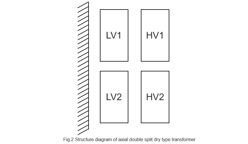
As shown in Figure 2 (original reference), the low - voltage winding has two axially - distributed branches on the same core. Branches have no electrical but magnetic coupling (degree depends on structure ²), and can be segmental or wire - wound. The high - voltage winding has two parallel branches matching the low - voltage ones, with similar specs and total capacity equaling the transformer’s.
2.1 Axial Double - Split Dry - Type Transformers
With a symmetrical structure and uniform leakage flux, it performs well in through/half - through operation. Large impedance between axially - split branches reduces short - circuit currents, ensuring one branch can run if the other fails.
However, its high - voltage winding (two parallel windings) doubles turns but halves conductor cross - section vs conventional. A 35kV D - connected design faces winding production issues (turn control, low efficiency), affecting safety/reliability.
Also, upper/lower low - voltage windings (arranged vertically) have ~20K temperature difference (upper hotter due to air convection). So, design/manufacturing needs enhanced temperature - rise checks and proper insulation selection.
2.2 Radial Double - Split Dry - Type Transformers
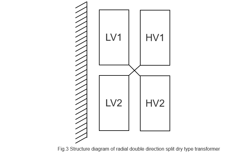
Common radial double - split dry - type transformers (structural layout in Fig. 3) have two radially - distributed low - voltage winding branches (usually wire - wound, due to structural specificity) and a single integral high - voltage winding.
The high - voltage winding, with normally - selected turns and conductor cross - section, boasts better winding process/efficiency than axial double - split types. Its near - perfect symmetry ensures good ampere - turn balance in through/half - through operation, plus uniform low - voltage winding temperature rise.
Yet, radially - split low - voltage windings have small division impedance and large coupling capacitance, increasing inter - winding interference. This impacts output power quality and inverter component reliability, requiring adjustments to the inverter - side control loop and system.
2.3 Special Double - Split Dry - Type Transformers
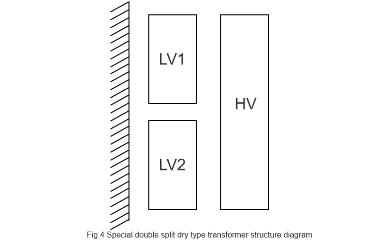
Fig.4 depicts a hybrid design combining axial (segmental/wire - wound low - voltage) and radial (single high - voltage) splits. This hybrid addresses radial low - voltage and axial high - voltage issues, reducing costs and improving manufacturing efficiency.
However, half - through operation (e.g., due to environmental factors or inverter faults) causes severe ampere - turn imbalance, leading to end - winding leakage flux and overheating. This design is thus high - risk.
3 Conclusion
Grid - connected PV transformers primarily use two - winding (step - up, D, y11) or double - split configurations. Key recommendations for double - split designs:
Maintain sufficient low - voltage division impedance for power quality.
Account for axial split temperature differentials in insulation selection.
Use Y, d11d11 for 35kV applications.
Avoid special hybrid designs due to half - through operation risks.


