• Product
  • Suppliers
  • Manufacturers
  • Solutions
  • Free tools
  • Knowledges
  • Experts
  • Communities
Search


1-30KW off-gird wind power controller

  • 1-30KW off-gird wind power controller

Key attributes

Brand Wone Store
Model NO. 1-30KW off-gird wind power controller
Input Voltage DC240V
Power 3KW
Series WW

Product descriptions from the supplier

Description

Features

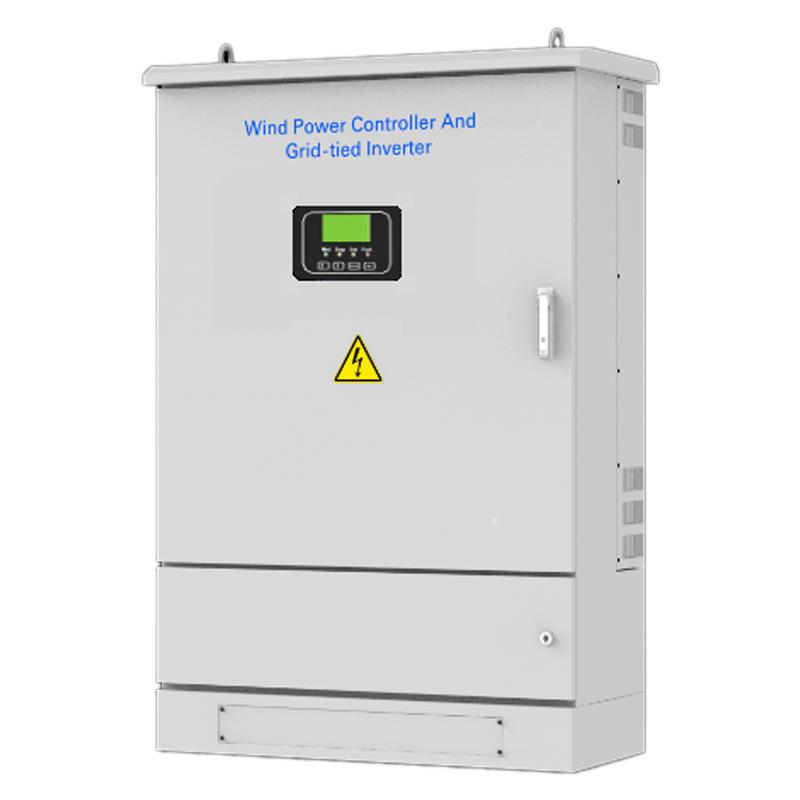
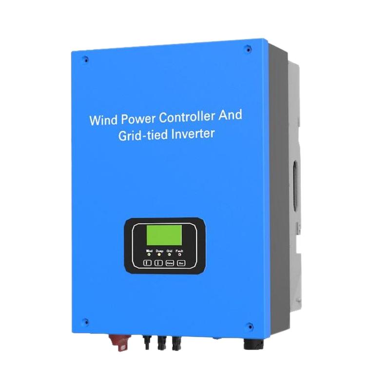
  • Can be applied to grid-tied system, off-grid system and grid-tied energy storage system.

  • R5232/RS485/RJ45/GPRS/Bluetooth/Zigbee optional.

  • MPPT power curve settable

  • protection function Standard

  • MODBUS protocol optional

Applications

  • independent wind power plant&independent household wind power generation system

  • Power supply for those unmanned regions like mobile communication station, high way, thecoastal islands,remote mountainous regions and border posts.

  • Regional research projects, government demonstration projects, landscape lighting projects forthose places with insufficient power or power shortages.

Technology Parameters

Model

WW10 - 48 - 48

WW20 - 48 - 48

WW20 - 48 - 240

WW30 - 48 - 240

WW30 - 120 - 120

WW30 - 240 - 240

WW50 - 240 - 240

Type

Boost

Boost

Buck

Buck

Boost

Buck

Rated input power

1kW

2kW

3kW

5kW

Rated input voltage

56VDC

56VDC

280VDC

280VDC

280VDC

280VDC

280VDC

Input voltage range

12 ~ 64Vdc

12 ~ 64VDC

60 ~ 320VDC

60~320VDC

30~160VDC

60~320VDC

60~320VDC

Rated input current

21Adc

42A

9A

13A

25A

13A

9A

Brake by hand

Keep press the button for 5s to unload completely, and then recover by hand.

Switch “ON” the brake switch

Brake by over current

25A (factory default, 0~25A settable).

50A (factory default,

0~50A settable)

10A (factory default,

0~10A settable

15A (factory default,

 0~15A settable)

30A (factory default,

 0~30A settable)

15A (factory default,

 0~15A settable)

10A (factory default, 0~10A settable)

Brake by overvoltage

Refer to "output overvoltage" control

320VDC (factory default,220V~320VDC settable)PWM unload step by step once reached the set unload voltage, and it will unload completely if the voltage rise 20V more.

Refer to "output overvoltage" control

320VDC (factory default,220V~320VDC settable)PWM unload step by step once reached the set unload voltage, and it will unload completely if the voltage rise 20V more.

Brake by over wind speed (optional)

18m/s (0~30m/s settable). Unload completely when reached the set wind speed, and recover automatically after 10mins (and the speed should be less than 15m/s.)

Brake by over rotational Speed (optional)

500r/min (factory default, 0~1000r/min settable). Unload completely when reached the set rotational speed, and recover automatically after working 10mins.

Charge Parameters (optional)

Rated battery voltage

48VDC

48VDC

48VDC

48VDC

120VDC

240VDC

240VDC

Temperature compensation function (optional)

-3mV/°C/2V

-3mV/°C/2V

-3mV/°C/2V

-3mV/°C/2V

-3mV/°C/2V

-3mV/°C/2V

-3mV/°C/2V

Rated output voltage

48VDC

48VDC

48VDC

48VDC

120VDC

240VDC

48VDC

Start unload voltage

56VDC (factory default, 44V~64VDC settable)

56VDC (factory default, 44V~64VDC settable)

56VDC (factory default, 44V~64VDC settable)

56VDC (factory default, 44V~64VDC settable)

140VDC (factory default, 110V - 160VDC settable)

280VDC (factory default, 220V - 320VDC settable)

56V (factory default, 44V~64VDC settable)

Complete unloaded voltage

58VDC (factory default, add 2V to the start unload voltage)

58VDC (factory default, add 2V to the start unload voltage)

58VDC (factory default, add 2V to the start unload voltage)

58VDC (factory default, add 2V to the start unload voltage)

145VDC (factory defaulted add 5Vto the start unload

290VDC (factory default, add 10V to the start unload voltage)

58VDC (factory default, add 2V to the start unload voltage)

Max. Output current

21A

21A

21A

42A

25A

13A

105A

General Parameters

Rectifier mode

Uncontrolled rectifier
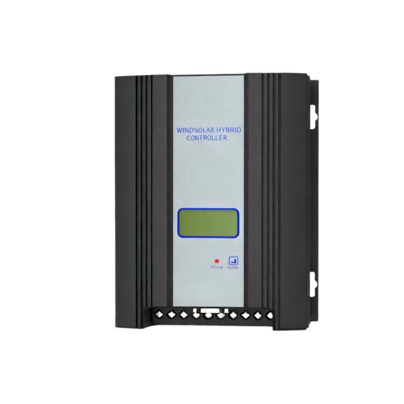
Display mode

LCD

Display information

DC output voltage, wind turbine voltage/current/power.

For those with charge control function, Battery voltage is showed as well.

Monitoring mode (optional)

RS232/RS485/RJ45/GPRS/ Bluetooth /Zigbee

Monitoring Contents

Real-time display: DC output voltage, wind turbine voltage/current/power.

For those with charge control function, Battery voltage is showed as well.

Parameter setting: Output overvoltage point, wind turbine over current point, wind turbine start voltage, and wind turbine brake settings.

Lightning protection

YES

Conversion efficiency

≥92%

Static loss

< 2W

< 5W

Ambient temperature

-20℃ ~ +40℃

-20℃ ~ +40℃

Humidity

5~95%, No condensing

0~90%, No condensing

Noise

≤65dB

Cooling mode

Forced air cooling

Installation mode

Wall - mounted

Cover protection class

IP42

Product dimension (WHD)

300x375x145mm

300x375x145mm

300x375x145mm

360x430x191mm

300x375x145mm

300x375x145mm

300x375x145mm

Product net weight

10kg

10kg

10kg

13kg

10kg

10kg

10kg

Dump load dimension (WHD)

360x80x120mm

300x400x210mm

300x400x210mm

400x390x210mm

400x390x210mm

400x390x210mm

400x390x210mm

Dump load net weight

2.8kg

9kg

9kg

12kg

12kg

12kg

9kg

Note: Part of parameters can be adjusted according to customer's specific demand.


Know your supplier
Online store
On-time delivery rate
Response time
100.0%
≤4h
Company overview
Workplace: 1000m² Total staff: Highest Annual Export(usD): 300000000
Workplace: 1000m²
Total staff:
Highest Annual Export(usD): 300000000
Services
Business Type: Sales
Main Categories: Wire cable/High Voltage Electrical Apparatus/Low Voltage Electrical Apparatus/Instrument meters/New energy/Tester/Integrated Electrical Equipment/Production equipment/Generator/Electrical fittings/Instrument Transformer/Equipment Parts
Whole life care manager
Whole-life care management services for equipment procurement, use, maintenance, and after-sales, ensuring safe operation of electrical equipment, continuous control, and worry-free electricity consumption.
The equipment supplier has passed platform qualification certification and technical evaluation, ensuring compliance, professionalism, and reliability from the source.

Related Products

Related Knowledges

  • Faults and Handling of Single-phase Grounding in 10kV Distribution Lines
    Characteristics and Detection Devices for Single-Phase Ground Faults1. Characteristics of Single-Phase Ground FaultsCentral Alarm Signals:The warning bell rings, and the indicator lamp labeled “Ground Fault on [X] kV Bus Section [Y]” illuminates. In systems with a Petersen coil (arc suppression coil) grounding the neutral point, the “Petersen Coil Operated” indicator also lights up.Insulation Monitoring Voltmeter Indications:The voltage of the faulted phase decreases (in
    01/30/2026
  • Neutral point grounding operation mode for 110kV~220kV power grid transformers
    The arrangement of neutral point grounding operation modes for 110kV~220kV power grid transformers shall meet the insulation withstand requirements of transformer neutral points, and shall also strive to keep the zero-sequence impedance of substations basically unchanged, while ensuring that the zero-sequence comprehensive impedance at any short-circuit point in the system does not exceed three times the positive-sequence comprehensive impedance.For 220kV and 110kV transformers in new constructi
    01/29/2026
  • Why Do Substations Use Stones, Gravel, Pebbles, and Crushed Rock?
    Why Do Substations Use Stones, Gravel, Pebbles, and Crushed Rock?In substations, equipment such as power and distribution transformers, transmission lines, voltage transformers, current transformers, and disconnect switches all require grounding. Beyond grounding, we will now explore in depth why gravel and crushed stone are commonly used in substations. Though they appear ordinary, these stones play a critical safety and functional role.In substation grounding design—especially when multiple gr
    01/29/2026
  • Why Must a Transformer Core Be Grounded at Only One Point? Isn't Multi-Point Grounding More Reliable?
    Why Does the Transformer Core Need to Be Grounded?During operation, the transformer core, along with the metal structures, parts, and components that fix the core and windings, are all situated in a strong electric field. Under the influence of this electric field, they acquire a relatively high potential with respect to ground. If the core is not grounded, a potential difference will exist between the core and the grounded clamping structures and tank, which may lead to intermittent discharge.I
    01/29/2026
  • Understanding Transformer Neutral Grounding
    I. What is a Neutral Point?In transformers and generators, the neutral point is a specific point in the winding where the absolute voltage between this point and each external terminal is equal. In the diagram below, pointOrepresents the neutral point.II. Why Does the Neutral Point Need Grounding?The electrical connection method between the neutral point and earth in a three-phase AC power system is called theneutral grounding method. This grounding method directly affects:The safety, reliabilit
    01/29/2026
  • What’s the Difference Between Rectifier Transformers and Power Transformers?
    What is a Rectifier Transformer?"Power conversion" is a general term encompassing rectification, inversion, and frequency conversion, with rectification being the most widely used among them. Rectifier equipment converts input AC power into DC output through rectification and filtering. A rectifier transformer serves as the power supply transformer for such rectifier equipment. In industrial applications, most DC power supplies are obtained by combining a rectifier transformer with rectifier equ
    01/29/2026

Related Solutions

  • Dedicated Vacuum Contactor Solution for Port Shore Power Systems
    I. Background and Challenges​Shore power systems have become core technical equipment for ports to reduce carbon emissions and noise pollution. However, these systems face two major challenges in the harsh operational environment of ports:​Severe Environmental Corrosion: High humidity and salt spray in port areas cause serious corrosion to metal components and enclosures of electrical equipment, significantly impacting electrical lifespan and operational reliability.​High Switching Requirements:
    09/13/2025
  • ABB Vacuum Contactor KC2 Power Supply System Technical Transformation Plan
    Issue Overview​The 10kV air compressor starting system of a company utilizes the ABB vacuum contactor KC2 as the control component for the operating circuit. The dedicated wide-voltage power supply module paired with this contactor presents the following issues:​Frequent failures: The power supply module fails to properly transition the voltage from 300V to 12V, resulting in fuse blowouts.​Poor heat dissipation: Enclosed installation of the module leads to insufficient heat dissipation, acceler
    09/13/2025
  • Solution for Medium-Voltage Motor Control and Protection Using Vacuum Contactor-Fuse (VCF) in a Coal Conveying System
    1.Project BackgroundA coal conveying system comprises 15 belt conveyors driven by medium-voltage motors. The system operates under complex conditions, with motors often subjected to heavy loads and frequent starts. To address these challenges and achieve effective control and reliable protection during motor startup, the project comprehensively adopts Vacuum Contactor-Fuse (VCF) combination devices for the 6kV medium-voltage motor power distribution. This solution details the technical features,
    09/13/2025
Haven't found the right supplier yet? Let matching verified suppliers find you. Get Quotation Now
Haven't found the right supplier yet? Let matching verified suppliers find you.
Get Quotation Now
Send inquiry
+86
Click to upload file
Download
Get the IEE Business Application
Use the IEE-Business app to find equipment, obtain solutions, connect with experts, and participate in industry collaboration anytime, anywhere—fully supporting the development of your power projects and business.