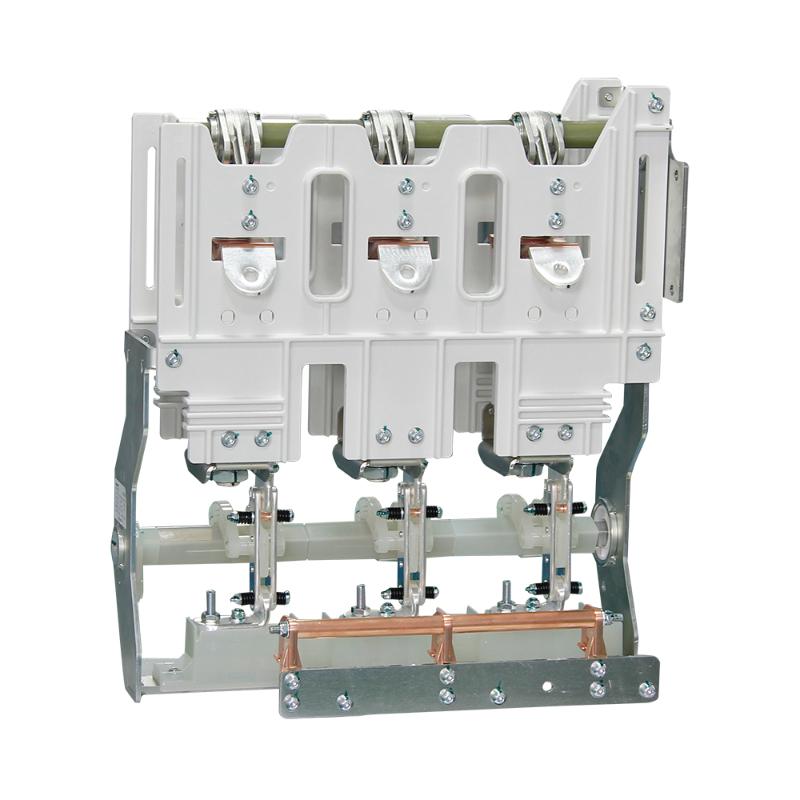
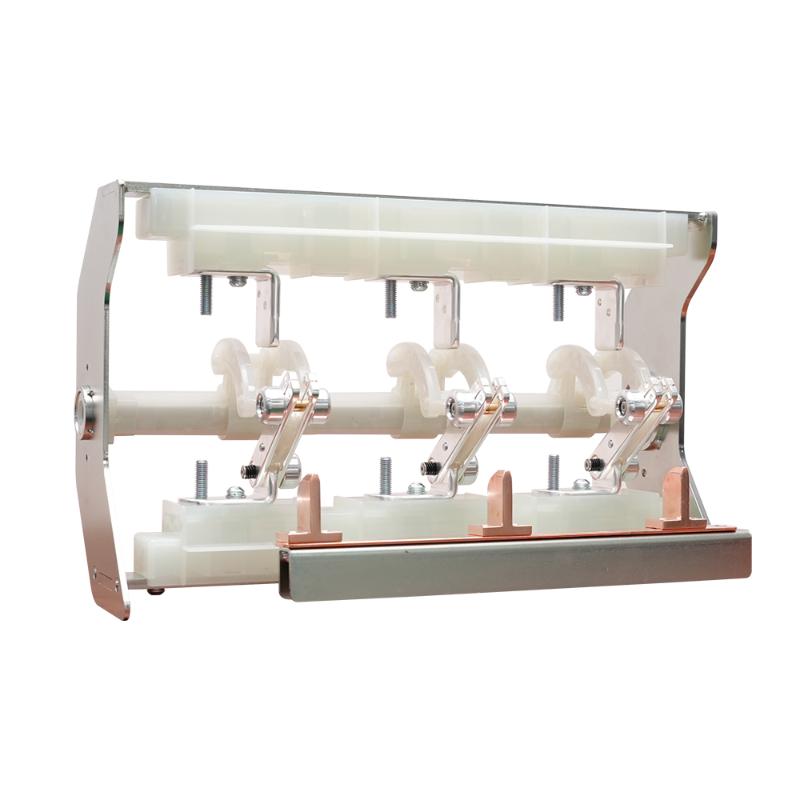
1-Core Straight throught joint kit


Key attributes
| Brand | Switchgear parts |
| Model NO. | 1-Core Straight throught joint kit |
| Rated voltage | 8.7/15kV |
| number of core | 1-core |
| Series | JSY |
Product descriptions from the supplier
Use and characteristics
Heat shrinkable medium voltage products are widely used for insulation treatment of 6-35kV cross-linked cable terminals and intermediate connections. It has the characteristics of small size, light weight, reliable operation, and easy installation. According to user needs, multi-core cables, dual ground wire structures, or products with special requirements can be designed.
Product name |
Applicable cable cross section(mm²) |
Indoor termination kit 1-Core |
|
1 |
10KV XPLE heat ahrinkable cable accessories |
25~50 |
JSY-10/1.1 |
2 |
70~120 |
JSY-10/1.2 |
|
3 |
150~240 |
JSY-10/1.3 |
|
4 |
300~400 |
JSY-10/1.4 |
|
5 |
500~630 |
JSY-10/1.5 |
|
6 |
20KV XPLE heat ahrinkable cable accessories |
25-50 |
JSY-20/1.1 |
7 |
70-120 |
JSY-20/1.2 |
|
8 |
150-240 |
JSY-20/1.3 |
|
9 |
300-400 |
JSY-20/1.4 |
|
10 |
35KV XPLE heat ahrinkable cable accessories |
50-120 |
JSY-35/1.1 |
11 |
150-300 |
JSY-35/1.2 |
|
12 |
400-500 |
JSY-35/1.3 |
|

Related Products
-
RNV-B1-12 GIS Sf6 Break Switch Circuit Breaker for Gas Insulated Switchgear
-
RNN-12 630A SF6 Gas Insulated Load Isolation Switch
-
RNN-12 SF6 Gas Insulated Load Isolation Switch (with Grounding)
-
RNV-A1-12D-1250A SF6 High Voltage Gas Insulated Inflatable Cabinet Circuit Breaker
-
24kV GIS Sf6 Break Switch Circuit Breaker for Gas Insulated Switchgear
-
24kV SF6 gas insulated load isolation switch (three position with isolation)
-
40.5kV Manual Operation Mechanism for Spring-Loaded Inlet of SF6 Gas-Insulated Switchgear
Related Knowledges
-
 Main Transformer Accidents and Light Gas Operation Issues1. Accident Record (March 19, 2019)At 16:13 on March 19, 2019, the monitoring background reported a light gas action of No. 3 main transformer. In accordance with the Code for Operation of Power Transformers (DL/T572-2010), operation and maintenance (O&M) personnel inspected the on-site condition of No. 3 main transformer.On-site confirmation: The WBH non-electrical protection panel of No. 3 main transformer reported a Phase B light gas action of the transformer body, and the reset was ineff02/05/2026
 -
 Faults and Handling of Single-phase Grounding in 10kV Distribution LinesCharacteristics and Detection Devices for Single-Phase Ground Faults1. Characteristics of Single-Phase Ground FaultsCentral Alarm Signals:The warning bell rings, and the indicator lamp labeled “Ground Fault on [X] kV Bus Section [Y]” illuminates. In systems with a Petersen coil (arc suppression coil) grounding the neutral point, the “Petersen Coil Operated” indicator also lights up.Insulation Monitoring Voltmeter Indications:The voltage of the faulted phase decreases (in01/30/2026
 -
 Neutral point grounding operation mode for 110kV~220kV power grid transformersThe arrangement of neutral point grounding operation modes for 110kV~220kV power grid transformers shall meet the insulation withstand requirements of transformer neutral points, and shall also strive to keep the zero-sequence impedance of substations basically unchanged, while ensuring that the zero-sequence comprehensive impedance at any short-circuit point in the system does not exceed three times the positive-sequence comprehensive impedance.For 220kV and 110kV transformers in new constructi01/29/2026
 -
 Why Do Substations Use Stones, Gravel, Pebbles, and Crushed Rock?Why Do Substations Use Stones, Gravel, Pebbles, and Crushed Rock?In substations, equipment such as power and distribution transformers, transmission lines, voltage transformers, current transformers, and disconnect switches all require grounding. Beyond grounding, we will now explore in depth why gravel and crushed stone are commonly used in substations. Though they appear ordinary, these stones play a critical safety and functional role.In substation grounding design—especially when multiple gr01/29/2026
 -
 Why Must a Transformer Core Be Grounded at Only One Point? Isn't Multi-Point Grounding More Reliable?Why Does the Transformer Core Need to Be Grounded?During operation, the transformer core, along with the metal structures, parts, and components that fix the core and windings, are all situated in a strong electric field. Under the influence of this electric field, they acquire a relatively high potential with respect to ground. If the core is not grounded, a potential difference will exist between the core and the grounded clamping structures and tank, which may lead to intermittent discharge.I01/29/2026
 -
 Understanding Transformer Neutral GroundingI. What is a Neutral Point?In transformers and generators, the neutral point is a specific point in the winding where the absolute voltage between this point and each external terminal is equal. In the diagram below, pointOrepresents the neutral point.II. Why Does the Neutral Point Need Grounding?The electrical connection method between the neutral point and earth in a three-phase AC power system is called theneutral grounding method. This grounding method directly affects:The safety, reliabilit01/29/2026


