• Product
  • Suppliers
  • Manufacturers
  • Solutions
  • Free tools
  • Knowledges
  • Experts
  • Communities
Search


10kV Three-phase Oil-immersed Low-loss Energy-saving Distribution Transformer

  • 10kV Three-phase Oil-immersed Low-loss Energy-saving Distribution Transformer

Key attributes

Brand ROCKWILL
Model NO. 10kV Three-phase Oil-immersed Low-loss Energy-saving Distribution Transformer
Rated voltage 10kV
Rated frequency 50/60Hz
Rated capacity 400kVA
Series S11

Product descriptions from the supplier

Description

Product Description

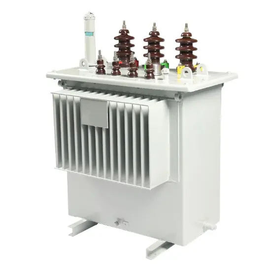
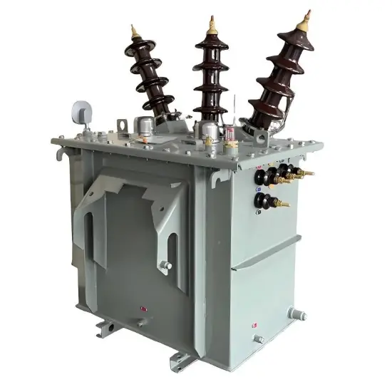
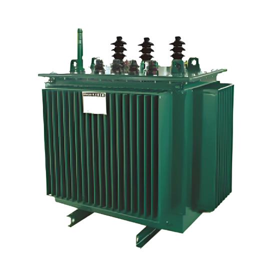
The 10kV Three-phase Oil-immersed Low-loss Energy-saving Distribution Transformer is a core component of modern power distribution networks, engineered for superior efficiency and reliability. Utilizing advanced core materials and an optimized design, it significantly reduces no-load and load losses compared to standard models. This transformer delivers substantial energy savings and lower operating costs over its lifespan, making it an economically smart and environmentally responsible choice for utilities and industries aiming to enhance the sustainability of their power infrastructure.

Product model

  • S: Three-phase Oil-immersed

  • 11: Performance Level

  • M: Fully Sealed

  • □: Rated Capacity (kVA)

  • □: Voltage Class (kV)

Conditions of use

  • Altitude: No more than 1000m, indoor or outdoor.

  • Ambient temperature: The highest ambient air temperature is +40℃, the highest daily average temperature is +30℃

  • maximum annual average temperature is +20℃, and the minimum temperature is -25℃.

  • Transformers can be provided to operate under special conditions according to user requirements.

Key Technical Features

  • Advanced Low-Loss Core Design:Constructed with high-grade, low-loss amorphous alloy or high-permeability silicon steel core, which dramatically reduces no-load (core) losses, the primary source of energy waste in transformers.

  • Optimized Energy Efficiency:Meets or exceeds stringent energy efficiency standards (such as IE3, IE4 or Chinese GB Standard). Its design minimizes total ownership cost by prioritizing high performance at both full and partial loads.

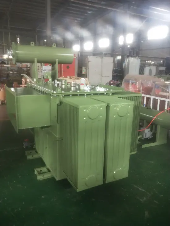
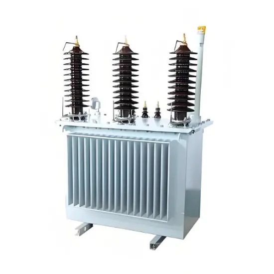
  • Robust Oil-Immersed Construction:The time-tested oil-immersed design provides excellent insulation and heat dissipation, ensuring stable operation, a long service life, and reliable performance under fluctuating load conditions.

  • Reduced Operating Costs:The significant reduction in energy losses translates directly into lower electricity bills, offering a rapid return on investment and a smaller carbon footprint.

  • Durable and Reliable Performance:Features a fully sealed tank to prevent oil oxidation, corrugated radiators for effective cooling, and high-quality components to ensure minimal maintenance and maximum uptime.

Performance Parameters: Technical Parameters of S11-30~1600/6~10/0.4 Series Oil-immersed Distribution Transformer


Rated Capacity

Voltage Combination and Tapping Range

Connection Group

No-load Loss (W)

Load Loss at 120℃ (W)

Short-circuit Impedance %

No-load Current %

Outline Dimensions 

(Length * Width * Height mm)

Total Weight (kg)

Foot Mounting Dimensions (mm)

High Voltage (kV)

Tapping Range %

Low Voltage (kV)

30

6

6.3

6.6

10

10.5

11

± 5

± 2×2.5


0.4

Dyn11

Yyn0

100

630/600

4.0

2.3

785 * 525 * 920

351

400 * 450

50

130

910/870

2.0

820 * 540 * 1000

442

400 * 450

63

150

1090/1040

1.9

850 * 565 * 1057

540

400 * 500

80

180

1310/1250

1.9

860 * 570 * 1125

549

400 * 500

100

200

1580/1500

1.8

910 * 635 * 1110

605

550 * 550

125

240

1890/1800

1.7

1020 * 645 * 1120

624

550 * 550

160

280

2310/2200

1.6

1045 * 675 * 1170

784

550 * 550

200

340

2730/2600

1.5

1105 * 745 * 1195

865

550 * 550

250

400

3200/3050

1.4

1145 * 745 * 1235

1018

550 * 600

315

480

3830/3650

1.4

1185 * 780 * 1290

1096

550 * 650

400

570

4520/4300

1.3

1295 * 835 * 1315

1466

550 * 650

500

680

5410/5150

1.2

1350 * 905 * 1410

1534

660 * 650

630

810

6200

4.5

1.1

1465 * 955 * 1475

1942

660 * 650

800

980

7500

1.0

1505 * 970 * 1595

2186

660 * 750

1000

1150

10300

1.0

1675 * 1140 * 1625

2394

660 * 850

1250

1360

12000

0.9

1735 * 1205 * 1805

3254

660 * 850

1600

1640

14500

0.8

1935 * 1290 * 1855

3800

820 * 950

Note: for transformers rated at 500 kva and below, the load loss values above the diagonal lines in the table apply to dyn 11 or yzn 11 connection groups, and the load loss values below the diagonal lines apply to yyno connection groups.

Typical Application Scenarios

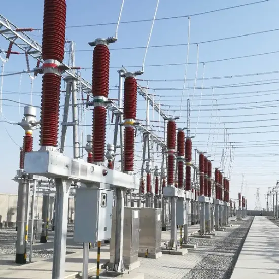
  • Public Utility Grids: Widely used in 10kV distribution substations for stepping down voltage to supply residential communities, commercial districts, and public facilities.

  • Industrial Power Supply: Serves as a dedicated power source for factories, manufacturing plants, and industrial parks where continuous operation and energy cost control are critical.

  • Renewable Energy Integration: Functions as a grid-connection point for distributed generation sources like solar and wind farms, where high efficiency is crucial for maximizing energy yield.

  • Infrastructure Projects: Provides reliable power for key infrastructure such as water pumping stations, railway systems, and airports, ensuring operational stability and energy savings.

Know your supplier
Online store
On-time delivery rate
Response time
100.0%
≤4h
Company overview
Workplace: 108000m²m² Total staff: 700+ Highest Annual Export(usD): 150000000
Workplace: 108000m²m²
Total staff: 700+
Highest Annual Export(usD): 150000000
Services
Business Type: Design/Manufacture/Sales
Main Categories: High Voltage Electrical Apparatus/Electric transformer
Whole life care manager
Whole-life care management services for equipment procurement, use, maintenance, and after-sales, ensuring safe operation of electrical equipment, continuous control, and worry-free electricity consumption.
The equipment supplier has passed platform qualification certification and technical evaluation, ensuring compliance, professionalism, and reliability from the source.

Related Products

Related Knowledges

  • Impact of DC Bias in Transformers at Renewable Energy Stations Near UHVDC Grounding Electrodes
    Impact of DC Bias in Transformers at Renewable Energy Stations Near UHVDC Grounding ElectrodesWhen the grounding electrode of an Ultra-High-Voltage Direct Current (UHVDC) transmission system is located close to a renewable energy power station, the return current flowing through the earth can cause a rise in ground potential around the electrode area. This ground potential rise leads to a shift in the neutral-point potential of nearby power transformers, inducing DC bias (or DC offset) in their
    01/15/2026
  • HECI GCB for Generators – Fast SF6 Circuit Breaker
    1.Definition and Function1.1 Role of the Generator Circuit BreakerThe Generator Circuit Breaker (GCB) is a controllable disconnect point located between the generator and the step-up transformer, serving as an interface between the generator and the power grid. Its primary functions include isolating generator-side faults and enabling operational control during generator synchronization and grid connection. The operating principle of a GCB is not significantly different from that of a standard c
    01/06/2026
  • Distribution Equipment Transformer Testing, Inspection, and Maintenance
    1.Transformer Maintenance and Inspection Open the low-voltage (LV) circuit breaker of the transformer under maintenance, remove the control power fuse, and hang a “Do Not Close” warning sign on the switch handle. Open the high-voltage (HV) circuit breaker of the transformer under maintenance, close the grounding switch, fully discharge the transformer, lock the HV switchgear, and hang a “Do Not Close” warning sign on the switch handle. For dry-type transformer maintenance: first clean the porcel
    12/25/2025
  • How to Test Insulation Resistance of Distribution Transformers
    In practical work, insulation resistance of distribution transformers is generally measured twice: the insulation resistance between thehigh-voltage (HV) windingand thelow-voltage (LV) winding plus the transformer tank, and the insulation resistance between theLV windingand theHV winding plus the transformer tank.If both measurements yield acceptable values, it indicates that the insulation among the HV winding, LV winding, and transformer tank is qualified. If either measurement fails, pairwise
    12/25/2025
  • Design Principles for Pole-Mounted Distribution Transformers
    Design Principles for Pole-Mounted Distribution Transformers(1) Location and Layout PrinciplesPole-mounted transformer platforms should be located near the load center or close to critical loads, following the principle of “small capacity, multiple locations” to facilitate equipment replacement and maintenance. For residential power supply, three-phase transformers may be installed nearby based on current demand and future growth projections.(2) Capacity Selection for Three-Phase Pole-Mounted Tr
    12/25/2025
  • Transformer Noise Control Solutions for Different Installations
    1.Noise Mitigation for Ground-Level Independent Transformer RoomsMitigation Strategy:First, conduct a power-off inspection and maintenance of the transformer, including replacing aged insulating oil, checking and tightening all fasteners, and cleaning dust from the unit.Second, reinforce the transformer foundation or install vibration isolation devices—such as rubber pads or spring isolators—selected based on the severity of vibration.Finally, strengthen sound insulation at weak points of the ro
    12/25/2025

Related Solutions

  • Intelligent Operation Solution for 12kV Vacuum Circuit Breakers: Integrating Real-time Monitoring & Lifetime Optimization
    Ⅰ. Equipment Operation & MaintenanceIntelligent Monitoring System Integration​Multi-parameter Real-time Monitoring: Embedded sensors (temperature, displacement, Hall effect current sensors) track contact temperature rise, mechanical characteristics (opening/closing speed, overtravel), coil current, and partial discharge signals. Data undergoes preprocessing via edge computing prior to cloud upload.​Lifetime Prediction Model: Dynamically evaluates remaining lifespan using electrical wear data
    06/10/2025
  • SF6 Circuit Breaker Solutions for Outdoor Installation (Anti-Pollution & Seismic Resistance)
    I.Core Challenges in Outdoor Installation​In high-voltage transmission and distribution systems, SF6 circuit breakers are exposed to complex outdoor environments for extended periods, facing the following critical issues:​Pollution & Insulation Degradation​Dust, salt fog, and industrial pollutants in outdoor environments easily adhere to equipment surfaces. In coastal or industrial areas, pollution levels may reach ​Class IV, resulting in insufficient creepage distance and triggering ​flasho
    05/12/2025
  • 12kV Indoor Vacuum Circuit Breaker Southeast Asia Solution: Anti-Corrosion Compact Design
    12kV Indoor Vacuum Circuit Breaker Southeast Asia Solution: Anti-Corrosion Compact DesignⅠ. Executive Summary​Southeast Asia faces rapidly growing electricity demand alongside environmental challenges including high temperatures, humidity, salt spray corrosion, and grid instability. This solution recommends ​Solid Insulated Pole-Mounted Vacuum Circuit Breakers (VCB)​​ featuring ​high reliability, ​compact design, and ​smart monitoring. Tailored for tropical climates and industrial scenarios, it
    06/10/2025
Related Free tools
Haven't found the right supplier yet? Let matching verified suppliers find you. Get Quotation Now
Haven't found the right supplier yet? Let matching verified suppliers find you.
Get Quotation Now
Send inquiry
Download
Get the IEE Business Application
Use the IEE-Business app to find equipment, obtain solutions, connect with experts, and participate in industry collaboration anytime, anywhere—fully supporting the development of your power projects and business.